Databases |
||
Articles, Newsletters, Etc. |
||
Pictures, Etc. |
||||
![]()
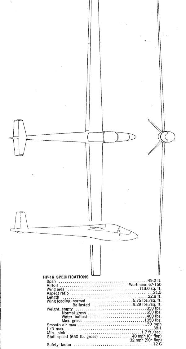
Soaring June 1971
The HP-16, which, of course, is being developed for amateur home construction from drawings or kits as the buyer opts, has the outward appearance of earlier Schreder designs such as the HP-11, but refinements are many.
The fifteen-meter wing is unique from several viewpoints. It is reminiscent of the beautiful FK-3, a German design flown at Marfa in 1968. Like the FK-3, it has an aluminum alloy wing skin bonded to plastic foam ribs with a minimum of riveting; but, there the similarity ends. The wing of the HP-16 is very smooth, although the closely-spaced ribs (four inches apart) can be detected in the reflection of the fluorescent shop lights in the shiny, unpainted aluminum surface. This is no doubt a result of the prototype having the skins pre-formed only at the leading edge radius. The 0.025 skin is merely pulled by hand around the ribs so that the first few inches of the rather sharp curvature must be pulled against the dribs with considerable pressure, and this causes the rippling between them which is probably of microscopic dimensions. The skin could be run lightly through a Farnham roll (I have one if you need it) or pulled somehow around a form in order to slightly pre-curve the metal; this would no doubt dispense with the slight rippling across the ribs. But it is doubtful if this would be necessary or even especially desirable.
The skins are bonded to the ribs with an appropriately gooey epoxy and are riveted to the starting aluminum spar. I say "starting" because, although the wing is intended to be built by builders from drawings or kits, Schreder has gone all out and had spars fully machined from a solid block of aluminum alloy, producing a very beautiful single-piece hollowed-out spar. Those who want to spend their time in building or buying a spar might do so using the older designs such as the HP-14 or the HP-11. The HP-16 spar is designed to carry all of the bending load of the wings; the skins and ribs stabilize and handle the drag loads and torsion. The 0.025 Dural sheet skins must be joined chord-wise at the quarter-span line because commercially-available sheets are only twelve feet long and each wing projects 23'6" outside the fuselage. Starting at the rear spar, this thin sheet is completely bent, carried around the leading edge, back to the rear spar underneath , and riveted both at the rear and main spar. Ribs are bonded with epoxy as was mentioned before. Each spar is made in two pieces so that it will not have to be 24 feet long, either; there is a permanent bolted joint at approximately the quarter-span joint which will interest those who plan to prang their wing tips. The quarter-span skin joints are butted with a doubler placed underneath and riveted in the usual well-proven Schreder manner. Pop rivets may be used as they are adequate for strength since the spar takes all the bending loads.
The foam ribs are made of closed-cell foam plastic and are machined in Dick's factory. His plant's machinery is designed for making French curves, Copenhagen ship's curves, railroad curves, and triangles for the drafting industry, so the contours are extremely accurate. The material is waterproof; this permits the inboard several feet of the leading edge ahead of the spar to be filled with water for ballast. It is merely necessary to provide a passage through the necessary ribs. A tube with holes in it, bonded through holes in the ribs, is used to put the water in and to drain it out at the bottom. At the top, another tube runs through which acts as a vent. Thus the water is baffled between the four-inch rib spacing and the wing skins are completely supported by the ribs throughout the water tank area; no other particular provision need be made for water ballast.
Unlike some earlier Schreder models, the flaps and ailerons of the HP-16 are tapered to match a two-to-one root-to-tip chord taper ration of the wing. They are also notable (unlike the HP-11 and HP-14) in retaining the "cusped" or hollowed-out shape of the airfoil section underneath the trailing portion. In order to permit this, since the flap skins carry the torsion loads of pulling them down, closely spaced plastic ribs are bonded inside the flap sections which are also made of 0.025 aluminum alloy sheet. The trailing edges of the flaps and ailerons are bonded and flush riveted on top and bottom. The rivets are there to prevent the bond from peeling. They are not to be thought of as a redundant or parallel structure to the bond, since the bond can easily carry the shear necessary for the hollow flaps to transmit torsion through their skins from the driving flap root rib on out along the hollow flap. The strength of the bonded joint alone is adequate to handle the loads as they are multiplied by the necessary factors required by official and sound design standards. This gives a beautifully sharp and smooth trailing edge, fully comparable to what we have seen with fiberglass wing construction. The flaps are segmented and slightly spaced span-wise so that there are several separate sections, each driving the other from pins as has been done since the HP-10 models. This permits the wing to flex even though the flaps are down ninety degrees. The segment spaces are, of course, taped for flight.
The wing, flap and aileron combination weighs under 100 pounds per side, I understand, but the striking preservation of the beautiful curvature of the Wortmann airfoil is obvious right on back to the line of the trailing edge. This is in contrast to earlier practice where Schreder straightened out and shortened the trailing portions to permit the empty flap to carry torsion through its skins. When the wing is applied to the fuselage, the flap root rib picks up a drive rib on the fuselage-mounted, flap-actuating cross shaft which makes it very easy to assemble the wing, since the flap need not be hooked up as a separate operation. The end of the wing is fitted with aileron counter-weights in the HP-14 with a flat downward tip plate to protect the counter-weight from contact with the ground when the aileron is up and to act as a skid on the HP-14. With the aileron and rudder counter-weights, the HP-16 looks as if it could go supersonic with nary a flutter. The inboard end of each wing spar is attached by two large diameter pins to a stub box spar that crosses the fuselage so that each wing is applied totally independently to the fuselage during rigging.
As to the fuselage, it is reminiscent of the HP-14 and HP-15, using the proven folding V-tail with its ingenious spring-loaded taper pins (one on each side) to hold it in position. On the other end is the also-proven retractable Schreder tow hook mounted in the nose (Hurrah!), and it takes what-ever old kind of ring that happens to be on the other guy's rope (hurrah again!). The superb retractable, pneumatic oil damped, long-travel, soft-action, shock-absorbed, landing gear strut is also retained from the HP-14. The excellent mechanical break and Tost wheel protrude with the wheel's entire diameter well below the fuselage to keep the belly out of the boondocks and to give the sing a nice angle of attack on takeoff. This angle of attack is relatively unimportant when one remembers that five or eight degrees of flap will get you off at a very reasonably slow speed, even if the wing does not have a large angle of attack. A hydraulic wheel break could be fitted and hooked up either to a hand squeezer on the stick or to heel pedal, according to the whim of the pilot builder.
And now let's go back again to the tail end and not forget the steerable tail wheel that has been such a joy to HP-14 owners. You can steer it right to your tie-down. Did I say tie-down? Yes, I did. This sailplane is mad of aluminum. Tie it down all summer and all winter, too, if you want to! Holes in the tip skid take a snap hook or clevis for instant secure tie-down.
The instrument panel is big enough to hold two rows of full-size instruments with room for a platen below for radio and oxygen regulator.
As on the HP-14, the landing gear retraction is on the right, the flap control on the left (mine will be like the HP-14 with a mechanical crank pinion and rack), but I believe Dick plans to provide a pump and hydraulic cylinder used on Slingsby-type HP-14s and on his later HP-15. Either way, it lets you put down the flaps in a second or two, should there be any reason for such a thing, and to release them instantly to get back that forty-to-one L/D should you be undershooting.
On the subject of flaps: You should find that 100-mph terminal velocity pretty interesting when you want to come down very steep through a wave window. Imagine spoilers with an area of fifteen square feet, but which reduce your landing speed ten miles per hour instead of increasing it that much.
Of course you must never slow up on approach so that you are hanging on the lift of the flaps and wouldn't be able to dump them. It is necessary to star around best L/D on approach, just as with spoilers. Then you can dump the flaps. Flaps down, nose down; flaps up, nose up. Keep the airspeed constant and you have the most versatile approach control of any aircraft built, let alone a sailplane. But the flare-out to landing, that's something else again. Slow down to thirty-five or thirty in the ground effect and roll her on with the tail three feet in the air if you choose, or "three point" her at your heart's content. If you do drop it in, you have that oleo strut to keep you from bouncing ten feet up again, and to prevent your reputation and your sailplane.
Construction of the fuselage is similar to, but simpler than, the HP-11 to HP-14. I believe it was Bill Stout, the designer of the Ford trimotor, who said, "simplicate and add lightness." The Ohio master simplicates as he adds lightness. The same square tubing sills are apparent; they are aluminum, but there are no welds this time. These are bolted and pop riveted to the fuselage sides, that is, pop riveted to the hefty one-sixteenth thick stretch-curved belly skin made all in one piece from sill around underneath to the other sill. Call it cast steel if you prefer -- rail-road rails and a boiler plate couldn't make it look stronger. You don't sit on bilges, either. A built-in seat bottom with the control cables passing underneath unscrews for inspection and screws back again for protection. If the bottom bends in due, say, to gear-up landing in a rock pile when you're asleep, there is some space between the HP's bottom and yours for the necessary crunching to take place. Where could you find a better place for a few extra inches?
For those who have built such fuselages as Schreder has offered over the years, the joint between the belly skin and the tail cone should not bother you; it's perfectly simple. Dick makes the flare on the '16's fuselage in less than fifteen minutes with a planishing hammer and a steel block. I think I could do it with my heel -- just a very slight flare and a multiple row of rivets.
As to its appearance. The lines are Dick's usual combination of practical beauty with a basic style that last and lasts, no sweep tails, no fancy curves or shapes to go out of vogue, just the appearance of flight at speed, of leanness and strength -- hard, bullet-like, slippery -- like a greased nail. I want one.
A VISIT TO DICK SCHREDER
"I make this report as a dedicated Schreder-watcher," writes Stephen du Pont, SSA Region One Director. Steve's involvement is something more than passive observation of the noted Ohio designer/builder/pilot. In addition to Steve's owning various HPs, his enthusiasm dates back to 1961 when he formed Helisoar Aircraft, Inc., to see the HP-10 through an ATC and into manufacture under license. "We carried the design 90 percent through certification with FAA and only terminated the project due to excessive expense combined with the realization that something much bigger was afoot in the sailplane world," her recalls.
For du Pont, the experience was a case of familiarity breeding admiration. As a result of detailed design and stress analysis of the HP-10, a five-year program of building two prototypes, tooling, and engineering drawings, he has an intimate knowledge of Schreder hardware and Schreder design philosophy.
Du Pont points out that in twenty years Schreder has designed and built by his own hand fourteen different sailplane models. Equally important, he has made them available to home builders in simple form and at modest cost. "He has not bothered with designs for the student pilot or the basement hacker," Steve emphasizes. "Rather, he has thought of the seasoned enthusiast, the intelligent instructor, the careful mechanic who wants to put his own time, instead of money, into a homebuilt sailplane."
Last month Steve and his brother Lex flew out to Bryan, Ohio, to see what was hatching in the HP aerie. It is clear from his report that he was deeply impressed. He wrote, "It is doubtful if the pioneering and development of anyone in this country has been so far reaching or so widely felt by so many serious soaring enthusiasts as has the work of Dick Schreder. His actions deserve a monument in recognition of one man's advancement of the art."