|
Separation Repair |
Gluing Skins to Ribs |
|
HP-16 (C-FWBH) Fix |
|
HOME-BUILDERS' HALL
(Soaring July 1980 starting on page 40)By STAN HALL
SEPARATION IN METAL-SKIN/FOAM-RIB BONDING (Part 1)
Bob fisher (of that famous solo transcontinental soaring expedition in 1961) reports that the metal-wings, leading edge skin on several HP-18s in the San Diego area has separated from the foam ribs, particularly in the areas right at the nose and a short distance aft. Since Bob is building an HP-18, he is concerned.
The skin on the HP-18 is bonded to the ribs via Hysol EA 9410 adhesive. Good stuff. The San Diego builders discovered the bond failures by tapping the skin at the ribs with a coin and listening for the "right" kind of sound. Instead of hearing a solid clunk they heard a tinny clink. In some cases they could press on the skin over a rib and feel it and see it move - and hear the joint creak. Message: no bond.
Apparently, one or more of these HP-18's was flying at the time Bob Fisher contacted this column, because he asked if aerodynamic forces were sufficient to pull the skin off the ribs.
Separation Case Histories
From the opposite end of the country a series of communications come from Steve duPont, author of the well-known book, Soaring by the Numbers, relating to essentially the same problem with his HP-18. Seems Steve purchased the sailplane already built. Shortly after purchase Steve began hearing strange in-flight popping noises coming from the wing. A careful inspection showed that what he was hearing was the skin breaking away from the ribs and probably some skin buckling. In some places the skin stood 1/8 inch of the rib. Not only that, the skin had also separated from the spar in some places, and over a period of time the aileron and flap trailing edge bonds are failed. Panic. Interestingly enough, though, the failures in the wing itself occurred aft of the nose, not right at the nose.
Back on the West Coast: Mac Snyder of Cupertino, California was installing the wing skins on his HP-18. He used the method traditionally to the installation of plywood skins on wooden, D-tube spars - he wrapped the skin around the leading edge and pulled aft by means of fabric straps (of a material similar to that used in auto seat belts) which he could tighten and which were attached to the flap/aileron sub-spar. He tightened and tightened, but the skin still came out short at the sub-spar, were it was to be riveted. He kept tightening until eventually the metal reached the required point. Imagine his chagrin when he discovered that in the process of hauling down on these straps he had managed to crush the foam ribs between the main and sub-spars! In my view none of these problems - the San Diego builders', Steve's, nor Mac's - can be traced to a design error. And neither can be reasonably be traced to aerodynamic forces, as Bob Fisher suggested. Although the aerodynamic forces can get pretty high in the leading edge, I seriously doubt they could get sufficiently high in any reasonable flight regime to pull the skin off the ribs. After all, the ribs on the HP-18 are only 4 inches apart. Considering also that they are spaced apart by foam members all attached to the skin, too, it looks like there is plenty of support to me. Rather, I believe these problems stem from improper technique in rib and/or skin preparation before assembly.
Checking Rib/Radial Intersections
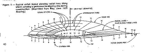
Homebuilders' Hall for May and June 1979 delineated a procedure for laying out airfoil contours from given ordinates. An important feature of one of the drawings accompanying the article (reprinted here as Figure 1) is that the radial lines connecting corresponding chord-percent points on the root and tip sections are straight.
What the article didn't say - because it dealt with drafting, no building - is that when the skin is bent to fit the contours, it will only bend in straight line elements (bend in one plane.) Thus, if a rib contour doesn't intersect the straight radial lines precisely as suggested in the figure (i.e., if the contour is either high or low) the skin won't fit down on the rib.
Before installing the skin, the builder needs to make sure that a strong thread, string, or wire stretched tightly from root to tip along corresponding chord-percent points touches every rib. If a give rib is below the string, the contours needs to be build up there; if there's bump or high place, it needs to be sanded down to the contour line.
I like to slip a .025-inch shim under the wire at the root and tip reference ribs so I can see a clearance between the string and the rib. When I see .025 clearance at all ribs, I have it made at that point and can move to another radial. If I lay the wire directly onto the reverence ribs, without the shims, the possibility exists that I could have a series of ribs that are all too high without noticing them until it come time to skin; thus the shims. A point at the leading edge itself (right on the intersection of the chord reference line and the contour) plus a couple between the leading edge and the main spar seem to meet my requirement for accuracy. But remember, if you use this technique, those points have to correspond, chord-percent-wise, from rib to rib.
Sanding for Accuracy
The way to get rib alignment in the first place is to install accurately-contoured and located ribs at the root, and at the tip, and about every four to six feet in between. These ribs serve as templates. The remaining foam ribs should be a tad oversize. Then, by us of a long, straight two-by-four with sandpaper rubber-cemented to one side, carefully sand the oversize ribs down the template ribs. A little watercolor paint on the template ribs will remind you not to sand them - until the very last, when a light touch will remove the coating. In sanding down to the template ribs, it is vital that the board always matches corresponding chord-percent points on the ribs as it is being moved. I couldn't possibly overemphasize the importance of this. For example, if the board is sanding at the 20 percent point on a particular rib it must also be sanding at the 20 percent point on all the other ribs. Otherwise, since the board is straight, you'll sand off places where you shouldn't - and end up with low spots. I move the board mostly in a chord-wise direction, with a span-wise movement only on occasion. In a tapered wing one would move the inboard end of the sanding board more then the outboard end - since the chord is greater there and the chord-percent points are farther apart.
Right about here would be a good place to interject a piece of information I have never before seen committed to paper - and I've seen a lot of paper.
Go back to Figure 1 and look at those radial lines again. Unless you're actually looking for it, you'll miss it completely, but another message these radial lines reveal is that aileron and flap spars need to be designed to fall on the same radial lines, too. That is, they need to fall on the same chord-percent points at both ends. Otherwise, the spars will have a bump in the middle. Try, sometime, building a spar that is not only tapered in a span-wise direction and slanted top and bottom to fit the airfoil contour - but it also humped in the middle!
I've seen tapered-wing sailplanes that have constant-chord ailerons. I'll wager their builders spit bullets. Because the root and tip aileron chords are the same - and the wing chords at those points aren't - the chord percentages of the spar location are greater at the inboard end than at the outboard end. If you were to lay a pair of spar lines (upper and lower edges) on a drawing such as Figure 1, and have the spar intersect each rib contour at the appropriate point, you'd see a pair of curved lines. This, amigo, is a humped spar. Guess how I found out.
I am informed that the foam ribs in the HP-18 kit come already contoured, and thus no sanding is required. But getting them all lined up via the tight string (I use .015 inch diameter music wire, stretched till it yells) is still a valuable, perhaps even vital, technique.
Preforming Skins
Having said all this, I doubt that improper rib contouring lies at the root of the skins not bonding properly to the ribs in those few reported HP-18's. I bring it up because it is a factor worthy of consideration in other foam-ribbed, metal (or plywood) skinned designs.
I suspect the problem lies in the skins of those 18's being improperly formed before installation. Just because the skin is thin (.025 in the HP-18) doesn't automatically infer it will bend exactly like you want it without effort. Sherb Klein, my resident expert on HP-18's, is inclined to agree.
On the other hand, Steve duPont tends to disagree, feeling that the skins, which come in the kit with the nose radius already formed, are okay as is, and that the de-bonding problem may lie elsewhere. More about this later.
HOME-BUILDERS' HALL (Soaring August 1980 starting on page 37)
By STAN HALL
SEPARATION IN METAL-SKIN/FOAM-RIB BONDING (Part 2)
As is rather widely-known among metal aircraft home-builders, the "accepted technique" for bending up a skin out in your garage goes something like this:
The skin is first laid out flat on the floor and the leading edge marked with a felt pen or other non-scratching marker. It is then turned over and one trailing edge is brought up and around to the other, forming a loop that looks like a fat streamlined section.
A wooden two-by-ten is placed on the loop near its highest point and pressed down so as to tighten the loop to the required radius at the nose. Some builders call in their friends and everybody stands on the two-by-ten and hops up and down until the proper radius is formed. Not very scientific, but apparently it works. That is, it works in cases where the radio o radius to skin gauge is fairly large, as is provided by most of the NACA and GA (General Aviation) airfoils.
Airfoil Accuracy and The Radius Problem
The problem with forming the proper radii for the popular FX-67K-150/170 airfoils (the HP-18 uses the -150) is that theses sections have very small nose radii. Also compared with the older airfoils, the upper ordinates increase very rapidly in the first 6 to 7 percent or so of the chord.
There is a certain minimum skin gauge that will carry the loads in a given design, and the thickness used on contemporary metal sailplanes carrying those sharp-nosed sections give a very small ratio of nose radius to skin gauge. This makes the radius, once formed, exceedingly difficult to adjust. The radius thinks it's a crease - and you know how difficult it is to adjust the dimensions of a crease. You not only have to get that radius just right, but the "radius" in the first 6 to 7 percent of the upper skin has to be formed, to, although maybe not so accurately. So now you have two formed radii instead of one - and getting that second radius with a two-by-ten can be challenging.
There's something else: The distance between the outstanding edges of the sheet, when the sheet is released after the guys get down of the two-by-ten must be right. This is a matter of experimentation and templates.
If you are forming the skin for a tapered wing, you have another problem; the nose radius gets smaller as you move outboard. Here, you need a nice touch with that two-by-ten - and you probably need to calibrate your friends by weight.
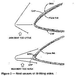
What causes the skin to stand away from the nose ribs in those reported HP-18's is likely, then, if you're prepared to accept some disagreement on the point, to be due to the metal being bent either too little or too much. If you'll refer to Figure 2, showing the nose of the FX-67X-170, you'll see what I mean. In the first drawing the skin is bent too little; the free ends are too far apart in the beginning. Because the skin is fairly stiff (particularly if the piece is the standard 12 feet in length), it wants to assume the approximate contour shown n the illustration when you install this skin over the leading edge. The only way to get it to lie down on the ribs is to use straps and pull like mad and use weights wherever practicable. But if you pull too hard, you risk crushing ribs - as Mac Snyder found out.
Also, even if you do get the skins where you want them, be prepared to hear some popping noises in flight. Even though the skin is thin, it contains some strong residual stress and it wants to unbend to its original free shape and, abetted by flight loads and maybe poorly crafted glue joints in the first place, that popping noise you hear will be the same ones Steve duPont has been hearing: bonds failing.
In the second figure, the skin is bent too much; the ends are too close when free. Here, the skin right at the nose won't come down onto the rib at all but sticks out, forward. There's simply no practical way to make this skin fit. And pulling on the straps will only damage the rib where the metal first comes into contact with it - and the inter-spar ribs as well.
In any and all cases, whether the skin is initially bent too little or to much, you'll lose that critical shape required at the leading edge.
Now, Sherb Klein of Redwood City, California, appears to have solved this problem, although it must be admitted that he hasn't yet installed the skins on his HP-18. But his technique looks like it ought to do the job.
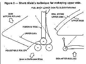
Sherb has the skins as received from Schreder reshaped on a Farnham Roll. As shown in Figure 3, he rolled along the upper sing skin only (mostly in the leading edge area, but actually over the whole chard), leaving the lower skin flat, as received. Since the smallest roller available on the Farnham was about 3/4 inch in diameter, and the nose radius on the rib much smaller than that, he rolled as close as he could get to the small skin radius already there. And he used templates, on for each end, for purposes of checking the contours. When the skins were removed from the Farnham, they had a shape nearly the same as the shape of the ribs. When he gets around to installing the skins on the wing, they should lie down on the ribs nicely.
Considering the cost of commercial shop time these days, one can see spending not a few bucks getting skins rolled on the Farnham. However, considering also the vital importance of Herr Wortmann's leading edge, perhaps it's worth it.
Bonding and Buckling
But maintaining Herr Wortmann's airfoil isn't the only consideration. There is also an important structural consideration - which brings us to Steve duPont's problem. That popping noise he has been hearing can only mean the structure is failing or has already failed.
Thin Metal structures can handle compressive and sheer load only if hey are prevented from buckling. And that's one of the things ribs and other internal structures are for. If the skin separates from on rib, say, the compressive and shear strengths of the skin between the two adjacent ribs still in action are but (roughly) a fourth of the original values. (The compressive strength of a Long Column - a term which carries a specific, technical definition - decreases as the square of its length.)
If the bonds on those ribs fail because they are now carrying the intermediate rib's loads as well as their own, maybe they will fail, too. And now we lose strength by an additional startling amount. This reminds me of the tale of the steel bridge, where one rivet failed, causing the adjacent rivet to become overloaded and fail, too. Eventually all the rivets failed in series and the bridge plunged into the river. No fun and games here.
Designing against skin buckling is one of the most important aspects of any structural design task. It is essential that the skin be firmly attached to all structures intended to stabilize it against buckling.
Through-the-Skin Repairs (Schreder's Response) (Udo Rumpf's Technique) (The HP-16 (C-FWBH) Fix)
As to repairing debonded areas: I am informed that the Sand Diego troops have come up with a fix - they drill a small hole in the skin at the point of debonding and squirt in a little epoxy by means of a hypodermic. For small repairs this is probably sufficient. For large repairs we might consider Steve duPont's technique.
Steve has come up with a different kind of fix, a time-consuming and patience-trying solution, to be sure, but a solution I think will yield more dependable results than simply going in with a hypodermic. And what we need is dependability.
Without the skin, the wing structure of the HP-18 looks like an egg create comprising many, man 3" by 4" boxes formed by the ribs, spars, and foam intercostals. Steve drills a 17/64-inch diameter hole (exact size not critical) in the skin at the center of each "box" that is loose and injects to the opposite skin a mixture of epoxy (International Paint Co., material number 4496-A and 4496-B) mixed 50-50 by volume with microballoons. He favors this adhesive over the Hysol EA 9410 because, he feels, the 9410 is too "runny."
First though, he scrubs the metal where the epoxy will eventually be in contact by means of a Dremel wire brush inserted into a nylon tube handle (scrubbed by hand, not by machine) and follows with an alchohol swab.
He then randomly globs the epoxy/micro into the skin/rib joint. In order to make the mixture go specifically where it is needed, Steve goes in afterward with a piece of bent, 1/8 inch diameter brazing rod that has been heated in water and dried. The epoxy won't stick to the heated rod and Steve can push it right into the open space between the rib and skin, making a generous, 3/8 inch fillet in the corner in the process.
Of course, since the access hole is only a tad over a quarter-inch in diameter, he has to do all this essentially by the Braille system. But he is able to check his progress occasionally by peeking through the hole via a grain-of-wheat bulb mounted on a wire and viewing the joint from the outside with a 120mm focal length lens. Brain surgery, anyone? And how does Steve get the goo through that tiny hole in the first place? Here's how:
With a quarter-inch diameter, round-ended bit in his router, he makes up a couple of matching, brooved blocks (Figure 4) which come together on alignment pens (nails). With the blocks laid out open-face-sandwich style, he fills the grooves with the epoxy/micro mixture. He then brings the blocks together on the alignment pins and clamps them together.
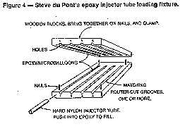
Next he pushes a curved quarter-inch diameter, hard nylon tube down into each of the epoxy-filled grooves. This, of course, forces the epoxy up into the tube. To prevent the nylon tubes from buckling as he pushes, he first insert them into a 4/8 inch I.D. metal tube.
Then Steve separates the blocks and removes the filled tubes. Next, he makes a spitball-sized plug from a piece of paper towel and inserts it into one of the tubes. This serves as a "piston," which Steve upon with a length of coat hanger wire. He inserts the tube through the hole in the skin, "aims" it and pushes on the wire. The epoxy comes out like heavy toothpaste. The tubes and other tools must, of course, be cleaned with alcohol or other appropriate dilutent after each use - and before the epoxy has a chance to set up - so that they may be used again.
Steve states that it took him an hour to do a hole, four sides - and he had 160 holes! All in all, a monstrous job. Steve still hasn't decided whether it mightn't have been easier, actually, to start over with new ribs and skins.
If there is a moral to this tale it might be: Don't glue anything down until first you make absolutely certain it fits just the way you want it. Check, double check, and check again.
When you make a mistake with a riveted joint, you can always drill out rivets. If you foul up in wood, you can always shave the mistake away. But when you err in metal-and -foam, the only remedy is to do like Steve did - or start over. You get one shot.
Epilogue
In reviewing the draft of this article, Steve has given the debonding problem additional thought. He is not convinced that the skins in the kit need reforming, and that if one follows Schreder's instructions exactly, one is not likely to experience debonding. However, he offers the following possibilities to a situation that is actually developing.
One possibility is, the skins are improperly cleaned before applying the adhesive. Of all the possible routes to debonding, this in Numero Uno. Two, the builder waits too long between cleaning and gluing, and the metal has a chance to oxidize, thus making the surface "dirty" again. Three, the builder inadvertently smears the adhesive off the metal and/or foam in the process of installing the skin.
There's a fourth possibility: Steve took his HP-18 to Hobbs one season with only a gray primer coat on the wings. The sun was so hot that to touch the wings was to burn the hand. Thus, Steve offers the possibility that the adhesive simply reached its softening temperature and let go.
My MA 9410 data, other than stating that the adhesive can be cured at temperatures up to 250 (which bears certain implications about strength), doesn't offer much in the way of information on strength at elevated temperatures. However, the data do show a tensile lap shear strength (aluminum-to-aluminum) of4750 psi at 75 degrees F and 1750 psi at 140 degrees F.
The data also show peel strength of 63 pounds per inch width at 75 degrees and 30 pounds per inch at 140 degrees F.
Other Hysol data state that the decrease in strength with temperature is fairly proportional.
Since the loading mode on the bond between skin and foam is too complex to identify as either "tensile shear" or "peel," one can only conjecture that 140 F (hot enough to burn the hand?) the "strength" of the adhesive is still likely to be higher than the "strength" of the foam. Nagging question: What is the strength of the foam at elevated temperature? And what about the fact that whereas aluminum alloy has a rather high coefficient of thermal expansion, foam has almost none at all?
Steve finds a measure of support for his suspicion of temperature from Ed Frappier. Ed states that in repairing damaged HP-18 wing structures he can, without damaging the foam, remove the skin with the aid of an air heat gun. So, maybe you can get more than one shot.
And speaking of support, Steve offers yet a fifth possibility for debonding - inadequate support of the wings in the trailer.
As concerns the integrity of metal-to-foam joints prepared by unskilled hands, it occurs to me that the jury is still out. Rivets, anyone?
HOME-BUILDERS' HALL (Soaring February 1980 starting on page 38)
By STAN HALL
A SUSPECT U-JOINT IN THE HP-18?
By the way of Les Sebald and Sherb Klein, HP-18 owner Bob Finch has contacted this column reguarding a potentially hazardous situation in the HP-18 elevator and aileron control system. Les, Sherb, and Bob strongly recommend the subject be brought to the attention of all HP-18 owners and builders. Here's the situation:
A combined push-pull and torque tube is connected to the side stick on the HP-18. Actually, because the tube has a designed-in "kink" in it, it is assembled of two tubes joined by a universal joint.
Bob writes, "In the process of performing a preflight inspection on my HP-18 one day, I made the horrifying discovery that one of the pins in the universal joint was at the point of dropping out. The pin had apparently not been properly headed over on the ends by Boston Gear, the manufacturer, and had slipped a full two-thirds of the way out."
Had he not discovered this fault during routine inspection, there is little doubt in Bob's mind that the pin would have fallen completely free in flight, inevitably causing loss of elevator and aileron control, a ship -- and maybe a live.
The Boston Gear universal (Part No. J50B) is, of course, non-aircraft and its use in aircraft control system applications is, in my opinion, questionable. Finch reports that Schreder has found a more suitable universal joint and will be using them on the HP-18 kits from now on. [See addendum at close of column] But this leaves the U-joints on existing HP-18's suspect.
Schreder is, of course, expected to contact all HP-18 owners and builders regarding the suspect part. However, since sailplanes have a way of changing owners without the designer's knowledge, the possibility exists that Schreder's list of owners is not current. This, under the assumption that all HP-18 owners read Soaring, Homebuilders' Hall takes this opportunity to issue an alert of its own, even though it may be redundant to do so.
In addition to the pin problem in the HP-18 universal, there may also be a strength problem in the joint. According to my 1976 Boston Gear catalog, the J50B universal joint has a static torque rating of 80 pound-inches at zero degrees operating angle. At 3 degrees, which is the approximate operating angle at neutral elevator of the HP-18 push-pull, rating drops to 62 pound-inches. At stick full back, the operating angle would be greater (can't tell from the drawing exactly how much), but if it doubled, the allowable torque would drop to 50 pound-inches.
One can produce 62 pound-inches of torque at the U-joint of the HP-18 by applying about 16 pounds side force on the stick. Question: how many panic-pounds can you apply, way, when wrenching the bird over to avoid a midair? -- 50 pounds? That's the load the FAA's Basic Glider Criteria recommends as a limit design load.
Builders wishing to replace the Boston Gear universal joint might consider using the MS-20271-B8 (formerly AN271-8) aircraft universal joint. I noted hat Aircraft Spruce and Specialty Co., Box 424, Fullerton, Calif. 92632 shows the part in its 1978 catalog. Price, $16.50. Expensive -- but maybe cheaper than the alternative.
As low as it is, that 16-pound side force mentioned above is misleading because, presumably, 16 pounds will fail the universal. And if you'll reread Homebuilders' Hall for January 1978, you'll note that the FAA requires that the part not fail until the load reaches a value 50 percent higher than that. It can yield on the way, the FAA says, so long as such yielding does not endanger the operation of the aircraft. But it must not fail before it gets there.
This being the case, and logically assuming that the manufacturers of commercial industrial hardware (like Boston Gear) never heard of the FAA and its limit and ultimate factors, loads, and stresses, and safe side load at the HP-18 stick computes to two-thirds of that 16 pounds, or about 11 pounds.
Aircraft Spruce's catalog shows a 675 pound-inch static torque capability of the MS20271-B8 universal joint at zero degrees operating angle. Although the catalog doesn't show rating at other angles, I would expect that torque connection factors, which can logically be assumed to be only angle-dependent, to be the same as for the Boston Gear part, namely; 1.0 for zero degrees, thence 0.1 per degree after that. The Boston Gear data stops at 30 degrees.
To figure the allowable torque at a given angle, simply divide the rated torque at zero degrees by the correction factor. In the case of the MS-20271-B8 U-joint, 3 degrees operating angle should yield 519 pound-inches of allowable torque, or about 130 pounds side force on the HP-18 stick.
Now, the 675 pound-inches capability at zero degrees for the MS-20271-B-8 (MS means "Military Standard") is quoted by Aircraft Spruce as a "minimum" capability. To me this means yield capability; it wouldn't be expected to fail below 50 percent over that, or 1012 pound-inches. Strong.
The MS-20271-B8 is not only strong, but permanently lubricated (the Boston Gear part isn't) and the moving parts are covered by a flexible boot out keep out dirt, rags, sandwich bags, alligators, etc.
In closing, here's a note from my private (meaning non-existent) file of Good Aircraft Design Practices: Non-aircraft quality hardware has no place in aircraft control systems, or anywhere else for that matter.
If the manufactures of commercial/industrial hardware had the kind of quality control that would yield parts having consistent strength, on to the other, a designer could use them in aircraft. No matter what the strength of the parts is, so long as one can depend on the strength quoted for it, a designer can feel confident in using it; he simply designs to the capability quoted. The trouble is, the manufacturers don't have the kind of quality control required -- which is why their hardware is cheaper than Aircraft hardware -- and why you can't depend on it.
Concerning the problem of the J50B universals, Dick Schreder writes:
"We have run tests on the J50B universals and find that they will carry loads up to 360 inch-pounds before yielding or failing at 5 degrees misalignment. Maximum possible pilot effort tests on the HP-18 stick have been measured to be 125 inch pounds. Actual flight loads encountered in 600 hours of flight of the prototype have never exceeded and estimated 15 pounds or 50 inch-pounds."
The following is a manufacturer's airworthiness directive that Dick Schreder has sent to all known HP-18 owner/builders on December 7, 1979:
"A report has been received that a pivot pin in the universal joint part number J50B used in the control stick actuating tube assembly was found to be loose and working its way out. Such an eventuality could cause complete loss of elevator and aileron control."
"All such universals should be inspected prior to each flight. Any increase in loss motion in the side-to-side movement of the stick could indicate that one of the two universal joint pins may have loosened."
"A better quality universal joint is now available. It has negligible backlash and is sealed to eliminate any possibility of being jammed by foreign matter. We recommend that all old universal joints be replaced before the next annual re-licensing of any HP-18."
"New universal joints, part number, MS20271B8S7711M manufactured by the Apex Machine & Tool Company of Dayton, Ohio, may be purchased from aircraft supply houses ....."
"The manufacturer of the MS 20271B8 has confirmed that they are capable of transmitting 600 inch-pounds of torsion and 1000 pounds of tension."
HOME-BUILDERS' HALL
(Soaring October 1974 starting on page 40)By STAN HALL
Having agreed that a flutter-free surface needs be balanced, light, and torsionally stiff, how do we go about designing to these requirements?
On the matter of balance: Ideally the surface should be balanced along its entire span to the extent that if the surface is visualized to comprise a series of disconnected chordwise elements, they would all balance about their common hinge line. A surface balanced in this manner is said to be "dynamically" balanced because, if the hinge line were to be suddenly accelerated, each portion of the balance weight and its associated part of the surface would be subjected to the same relative motion.
On production-type aircraft this is commonly done by incorporating a long, thin, lead slug into the leading edge. This often presents manufacturing problems, however, and unless the aircraft is capable of very high speeds, is rarely done where only a few units are involved.
In the case of low-speed aircraft and in the case of aircraft carrying small control surfaces (plus cases where production is limited), the use of a single "static" balance weight is common practice. If the surface has good torsional stiffness, it can be fooled into thinking that its whole leading edge is ballasted, even though the weight is concentrated at one point forward of the hinge.
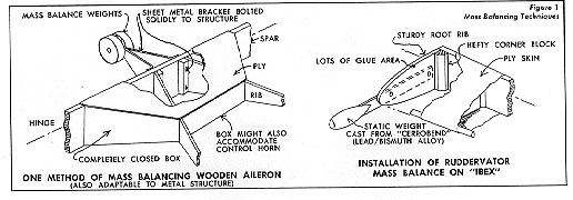
Two techniques for doing this are shown in Figure 1. The important thing here is, in addition to achieving balance, to secure the balance weight solidly to the structure. One iota of looseness, and the beneficial effects of balancing deteriorate right away.
The FAA also recommends that movable tabs be balanced. However, I don't think I'd go that far. Tabs are unusually light and undoubtedly have natural frequencies that are more than adequate for the purpose.
Obtaining light weight in the surface centers upon minimizing the weight aft of the hinge line, for this also requires less weight forward of the hinge line to balance it. Fabric covering is always better than wood or metal from the flutter standpoint simply because it is lighter. However, there are often compelling reasons for reversing this point of view-but they rarely involve only considerations of flutter.
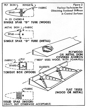
Figure 2 shows several techniques for obtaining torsional stiffness in control surfaces. Some of these use the D-tube technique commonly used in wings, while others employ a square or rectangular torque box located at or near the hinge line. Even solid spars can be used, although they are not efficient from the standpoint of weight. The flat truss shown is a particularly efficient technique from the standpoint of weight and is commonly used in ailerons. The figure also shows the technique I used on the ailerons of the Ibex. In this case the surface was simply too thin to permit the use of other than a stress-skin technique to obtain the desired torsional stiffness. I even filled the interior of the surface with polyurethane foam to stiffen the skins against buckling, although this was probably unnecessary.
To Balance or Not To Balance
The question inevitably arises as to what criteria should be used in deciding whether a surface should be balanced or not. It is extremely difficult if not impossible to generalize on this, and the problem is made no simpler by the fact that many sailplanes carry no balances at all in their control surfaces. However, it has been my observation (emphasize the term "observation") that non-balanced controls sailplanes tend toward maximum L/D's below 30 and design diving speeds below 120 miles per hour or so.
Sailplanes having performance in these regions seem also to tend toward sturdier aft fuselages, which make them very stiff both in bending and torsion. Thus, for all practical purposes, only one degree of freedom exists (control surface rotation about the hinge line) and, as indicated earlier, it takes at least two to flutter.
The fact that these sailplanes rarely exhibit flutter does not necessarily suggest that flutter was designed out of them on the basis of analysis or even test. It suggests, rather, that without being able to quote a number, designers have developed a "feel" over the years on how much stiffness a sailplane structure ought to have. Thus, a new designer will find it productive to spend plenty of time at the local gliderport studying the techniques used by the pro's.
Some sort of additional dividing line seems to exist regarding the ailerons. Not many sailplanes having spans below 15 meters and aspect ratios below about 20 have mass-balanced ailerons. Wings of these dimensions, although certainly not "stiff" in bending, are obviously stiffer than those having longer spans and higher aspect ratios. Thus, if the wing also has good stiffness in torsion, the aileron provides the only degree of freedom left.
This being the case, it probably doesn't need balancing unless, according to the OSTIV, the design diving speed is in excess of 200 km./hr. (108 knots, 124 mph). OSTIV also recommends that all control surfaces be balanced if the design diving speed is in excess of 240 km./hr. (130 knots, 149 mph). As indicated earlier, the FAA recommends only that the sailplane be flutter-free up to the design diving speed. OSTIV says 1.35 design diving speed.
Flutter-Proofing the Wing
Unlike a control surface, a wing can't be balanced about its "hinge line." Neither can it be made particularly light in weight because of the long cantilever span involved. This leaves only torsional stiffness as the prescribed therapy. As indicated last month, lack of torsional stiffness led the Ibex wing to flutter. So make it stiff.
One way to make a D-tube wing stiff (other than providing enough material) is to provide as much cross-section area as practicable in the for-ward part of the airfoil, i.e., use a thick airfoil with the spar well aft. The torsional shear stresses in the skin and spar are directly proportional to the enclosed area, and, if there is sufficient area to keep the shear stresses low, the D-tube will be "stiff" by definition. It is also important to provide a sufficient number of nose ribs to keep the skin from buckling between them.
If one plans to carry water ballast in the wing, it is best from a flutter point of view to stay inboard so as to keep the moment of inertia of the wing about the root as low as practicable. Carrying ballast in tip tanks (which has been done) is dynamite. This recommendation recognizes the fact that storing water inboard rather than outboard carries structural penalties to the extent that outboard carried ballast helps relieve wing bending moments and thus structural weight. However, this is simply another of the many elements in sailplane design that need trading off.
Flutter-Proofing the Control System
Control system flexibility and looseness in joints have very significant effects on flutter. For example, although low system friction is highly desirable from the pilot's point of view, high friction is good from the flutter standpoint because friction tends to inhibit it.
Using push-pull tubes in lieu of cables is also desirable, if you watch out for looseness in the joints, because cables are like long flexible springs. They add to the overall system flexibility and can, in some situations, actually abet flutter, once started.
I use 7 x 19 cables to drive the ruddervators on the Ibex. However, whenever there exists a long run between pulleys, I use a very stiff (7 x 7) cable. I did this in recognition of the partial degree of freedom (see September column) represented by Ibex's "flexible" boom. I doubt this stratagem would be necessary in a thicker-tailed fuselage.
By the way, tightening the cables will have absolutely no effect on their stiffness. Many builders (and designers, as well) often overlook this. A pound of force will stretch the cable the same amount whether it is rigged to 10 pounds or 100. It is simply a spring. However, tightening the cable does increase the friction -- which, as indicated earlier, helps damp out flutter. The only way to improve stiffness in a cable system is to use a large diameter cable or, for the same diameter, a coarser weave cable such as 7 x 7 as opposed to 7 x 19.
It is essential that looseness or free play be minimized in the hinges-and all the joints, for that matter. I make it a practice to ream all holes in the control system.
In its Basic Glider Criteria Handbook, the FAA requires the following test: If, when the cockpit control is blocked and finger pressure applied to the trailing edge to cause the surface to rotate, the trailing edge moves in excess of 2.5 percent of its chord, the system flunks the course. The same requirement holds true for the tabs.
Flutter-Proofing the Fuselage
Although fuselages don't flutter in a strict sense, they provide those blasted degrees of freedom if insufficiently stiff and can thus couple with wing and/or control surface degrees of freedom. And that's bad news.
The flight experience I described last month was the result of a mistake I made in the original design of the Ibex empennage in placing the static weights at the tips of the surfaces instead of at the roots. I simply didn't think that the surfaces would want to rotate about the boom's torsional axis. Such a simple, yet potentially disastrous oversight! As it turned out, the natural period of vibration of the surface-plus-boom combination was just low enough to oscillate under the influence of the inexhaustible supply of energy being extracted by the surfaces from the flow of air around them. Scary, let me tell you.
Fuselages that carry T-tails have always bugged me, particularly those having the incredibly small tail-end cross sections we see at the gliderport these days. Here, a large blob of weight sits atop the vertical tail. Obviously the mass moment of inertia of that weight about the fuselage torsional axis is high-at least several times higher than a horizontal tail placed down where it ought to be. Coupling this fact with the small fuselage cross-section and, well . . . thin ice.
Altitude Has Its Effects, Too
You wave-flying enthusiasts might be surprised to learn about some of the effects of high altitude on flutter. Here, surfaces can flutter even if they are balanced. This involves a speed-of-flight term known as critical Mach number. When you reach this speed, shock waves are produced on the wing upper surface which drastically distort the airflow, with the result that unsteady flow and buffeting can introduce forces that cause the surface to vibrate. The designers of high-flying commercial jetliners and military aircraft have to contend with this problem, and one way they solve it is to raise the critical Mach number by sweeping the surface leading edge.
High flying sailplanes are subject to critical Mach number conditions if they fly fast enough (which isn't really as fast as one might at first think) and/or if they operate at high lift coefficients typical of tight turns, pull-ups, etc.
The reason altitude plays a major role in this is that at a given true airspeed Mach number is primarily a function of temperature. The higher one flies the colder it gets, and the colder it gets the slower becomes the speed of sound (Mach 1.0).
The critical Mach number is the Mach number at which the aircraft is flying where the air at some critical point on the aircraft is flowing at the speed of sound, and this can be well below Mach 1.0 for the aircraft as a whole. Wing upper surfaces, for instance, have velocities over them which are considerably higher than those of the free stream. On the NACA 23015 airfoil, for example, the critical Mach number at zero angle of attack is about 0.58, which means that some part of the upper surface is experiencing Mach 1.0 while the rest of the wing is doing 0.58.
With increasing angle of attack, the airflow over the wing upper surface speeds up even more, causing the critical Mach number to occur at an even lower flight speed. At an angle of attack of eight degrees the NACA 23015 would have a critical Mach number of about 0.43.
A sailplane using the NACA 23015 airfoil and flying at 35,000 feet would, if flying at zero angle of attack, need indicate about 215 miles per hour (187 knots, 346 km./hr.) to reach the critical Mach number. At eight degrees angle of attack the indicated airspeed would be about 159 miles per hour (138 knots, 256 km./hr.).
Admittedly, this is tooling right along, but one not infrequently reads accounts of sailplanes approaching these velocities, mostly inadvertently. And what about tomorrow's sailplanes? They'll be cleaner and slicker and faster, no doubt about it. Consider, too, a high-altitude pilot nodding off from lack of oxygen in one of today's sailplanes and slipping off into a steep dive. Flutter City. Pilots of low-flying aircraft seldom have to worry about critical Mach number because the lower the altitude the higher the speed of sound and the less chance there is of reaching it. For low-speed aircraft the critical flutter speed is set predominantly by the indicated airspeed because this measures the energy in the airflow, and the energy in the airflow is what "fuels" the flutter.
Parenthetically, it is important to observe that any structure can be made to vibrate, regardless of all the things that might be done to prevent it. However, when all these things have been done, the possibility of vibrating under what we consider to be acceptable flight operating conditions is likely to be remote.
For high-speed aircraft there are two critical flutter speed limits, one limit established by indicated airspeed (because the energy of the airflow is still to be reckoned with) and the other by Mach number-because of incipient distortion of the airflow and consequent buffeting. This is why pilots of high altitude jets keep one eye on the indicated airspeed and the other on the Machmeter.