Adding Adjustable Rudder Pedals to the HP 14

By John de Jong

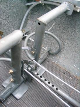
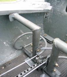
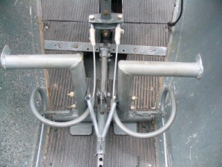
As most owners of HP 14 or earlier Schreder designs know these designs did not include rudder pedals that can be considered “adjustable”.  These designs had the pedal pivot points bolted to the floor, and the construction notes called for adjusting the pedal position on the floor to suit the builder.  The only way of changing the pedal “position” easily was to change which hole in the driver “strap” was picked up by the bolt on the pedals (this was a mod performed on our HP14 when we purchased it).

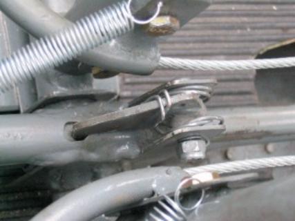
(Thanks to Bill Avoilo who submitted photos of the original system to the HP website.
I could not find photos of our original setup, but it was the same as this, except without the heel brake )

While this works, it has a number of problems

       The geometry of the system is poor when the neutral pedal angle is not near perpendicular to the straps.
       The pedal axle will likely be either ahead or behind of your feet depending on your leg length – making use uncomfortable over long periods of time.
      
When the pivot point is not at the pilot’s foot, movement of the entire foot is required rather than pivoting of the ankles.  This forces the pilot to move his whole legs – making the workload go up considerably.
      
When multiple pilots fly the aircraft unbolting the control linkages is required – and re-assembly with “unbalanced” or uneven pedals is possible - I’ve done it (one of those flights where almost all turns are in the same direction).
       In flight adjustability is impossible to reduce fatigue.

In our case, my partner (Alex) is ~6’, while I am 5’6” – leading to all of the above making the aircraft less than desirable for comfort when flying for long periods of time.  Combining this with the fact that the HP14 requires quite a bit of pedal travel for full inputs made 7hr flights quite demanding.

So Alex and I began an evolution of the pedal assembly to address these issues.

Our first modification added an adjustable pedal carriage that we still use today.  This allowed us to place the pedals in the ideal position for each of our physiques, but still used the standard HP 14 “straps” with bolts to make the adjustments.

This allowed us to address the issues of geometry and pedal pivot point, but still left us with issues on the ease of adjustability.


After flying with this setup for a number of years I finally found time last spring to take the project to the next stage – full adjustability, with no disassembly required.

Our biggest single challenge during this project was finding a way to add fully adjustable pedals in the most simple manner possible.    We extensively reviewed dozens of aircraft to see how it was done on them and found a number of issues.

The HP14 rudder mixer is under the instrument panel, not under the center fuselage, so the general pedal assembly design used on the HP18/RS15/ and other glider will not work without changes.

The HP14 rudder driver is in the center of the forward fuselage where on most aircraft the rudder cables travel down the outside of the fuselage – so reversing bellcranks/pulleys might be required.

We were not comfortable with increasing the complexity of mixer system anymore than it was, so after review we came up with a number of criteria:

1)     No additional pulleys
2)     No bellcranks for direction reversal or pedal travel reduction
3)     Minimum cable bend radii can not be exceeded where the cables are moving during use
4)     Full in-flight adjustment is highly preferable
5)     Pedal travel needs to be reduced as our aircraft was 5+ inches (normal on most modern ships is ~3”)

As is often the case, the solution was actually quite simple, but literally took us a couple of years of bashing ideas around to work out – and our biggest mistake was in not thinking in a three dimensional manner.

The solution turned out to have 2 parts – a new bellcrank, and change the shape of the “S” tubes that most adjustable pedal systems use.

Adding a new bellcrank to the rudder mixer above the floor was a modification made to the kits beginning with s/n 13 (ours was s/n 12).  We tailored the size of this bellcrank along with the size of the “S” tubes to give us ~3” of pedal travel.

This modification also eliminated the need for large holes in the cockpit floor which were previously necessary to route the straps from the pedals to the mixer underneath.  A side benefit is that the under-floor spaces won’t collect so much dirt/grass between annual inspections.


The key to making the system was to bend the “S” tubes in the third dimension.  This allowed us to keep the bend radii large and so prevent fraying of the cables, along with simplifying the system.

The “S” tubes in this case were formed around an acetylene bottle cap for the small radius, and a small 4 cylinder engine crank pulley for the large radius.

The “S” tubes were then welded to mounts that had been previously attached to the pedals, and return springs added so that the pedals cannot “fall” towards the pilot.

Front mounts were formed of 4130 steel, and bolted to the #1 bulkhead with doublers on the opposite side to distribute the loads.

With care during the crimping of the cables we were able to get the pedals so close to neutral that we have not been able to tell there is any problem when flying.


If we decide that we want to change the pedal angle, we can just shim the forward mounts to lengthen the available cable, and the pedals will angle more to the front bulkhead.

To make adjustment easy, the pedal carriage has a latch with redundant springs to allow easy movement.


The net results of all this work is much more enjoyable flying. Previously to roll into a turn aggressively required full pedal inputs, which forced the pilot to extend their foot to the point where it felt like you were pointing your toes at the nose.  Now the pedal inputs are very comfortable and have modest input travels.

Future modifications:  While the pedal assembly has proven itself to work well in the last season’s flying – there are still more changes that I wish to make.

The upper and lower carriage tubes are a little too close together allowing more movement to the pedals than I like (this was a design compromise from phase 1 of the mod).  This led me to add the aluminium “shoes” that can be seen in some of the photos under the center of the pedal assembly.  This has reduced the movement, but at the expense of make the pedals more difficult to move due to interference with the floor (the forward and rear mounts of the assembly are on different floor sections.   This spring I will move them probably ~1” further apart which should eliminate almost all of the movement, and will let us remove the shoes.


The final addition to make is to add a connection from the pedal latch to the instrument panel, making the pedals fully in flight or ground adjustable from the pilot’s seat.