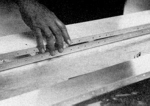
 Getting spar caps ready for assembly.
Building
The HP-18
Part Three
By Richard Schreder
Soaring May 1976, page 31-42
Last month's installment on building the HP-18 covered the construction of the tail (as well as extensive notes on building procedures). The idea was to break the ice for the novice builder by beginning with a simple assembly such as the tail. With this experience behind us, this issue will be devoted to the assembly and skinning of wings. Ready? Let's go.
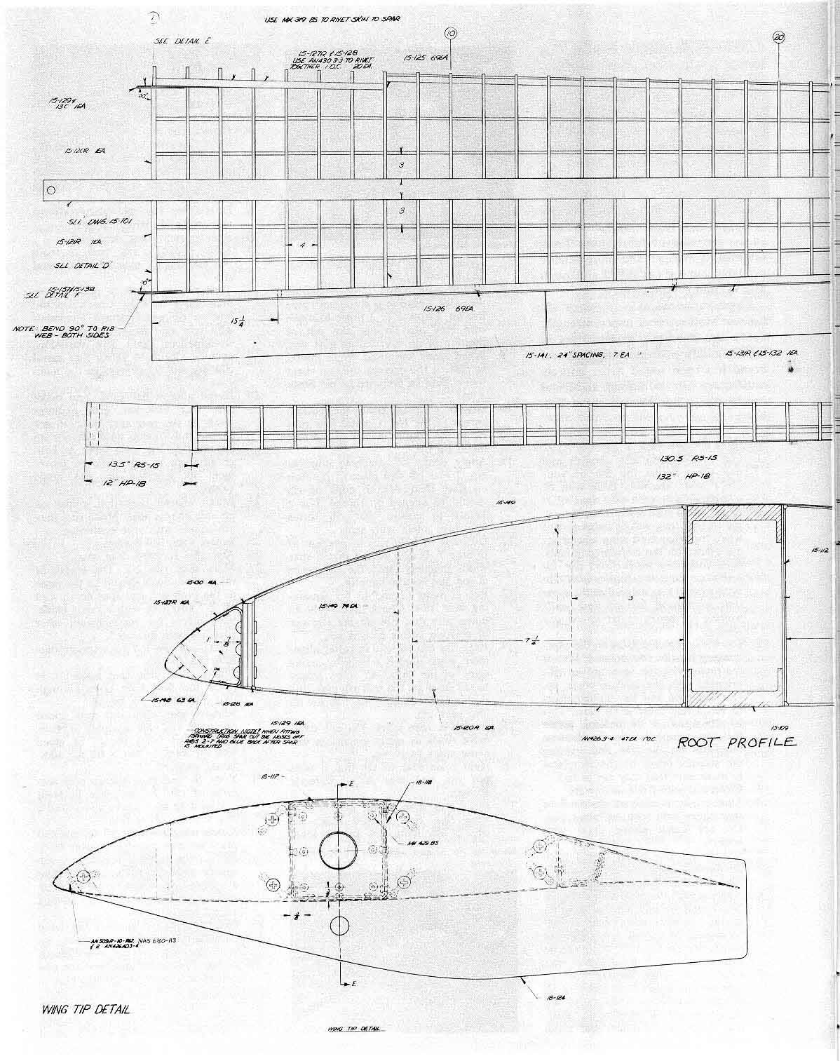
The HP-18 wing uses a simplified method of construction and is assembled without special jigs. An aluminum box spar carries the bending loads in the wing. The root and tip ribs are made of aluminum as are the rear spar and the short front spar which transmit the torsion and drag forces into the fuselage. All of the intermediate ribs are made of a polyvinylchloride plastic foam. The skins are .025-thick 2024-T-3 Alclad aluminum sheets preformed to the leading edge contour. The skins are continuous from the trailing edge, around the leading edge, and back to the trailing edge. There are only two sheets of aluminum covering each wing; these are glued and riveted at the butt joint where they come together at the midpoint of the wing panel. The skins are riveted to the front and rear drag spars and the two metal end ribs. They are attached to the main spars and foam ribs with epoxy adhesive. This method of construction eliminates the waviness that results from riveting all ribs in conventional metal wings. It also cuts down the assembly time by 50 percent or more. A further advantage is the elimination of much time-consuming filling necessary to smooth a fully riveted wing.
The wing kit consists of all materials necessary to build the wing. items that are already fabricated are:
Main spar caps and fittings
All wing ribs
Front and rear spars are bent and pilot drilled
Flap and aileron skins
Flap and aileron tip ribs
Wing skins
End fittings for push/ pull rods
Shear webs
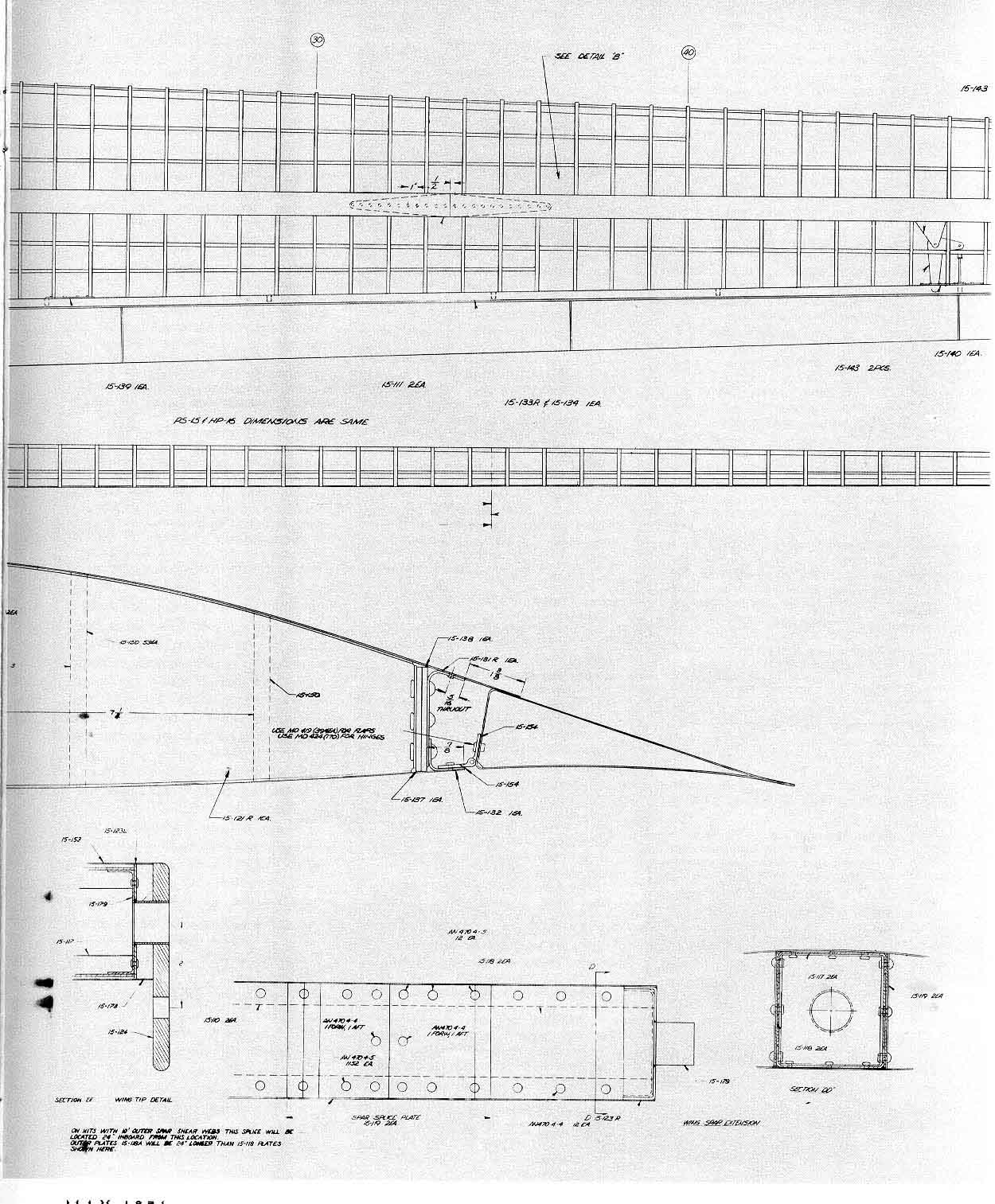
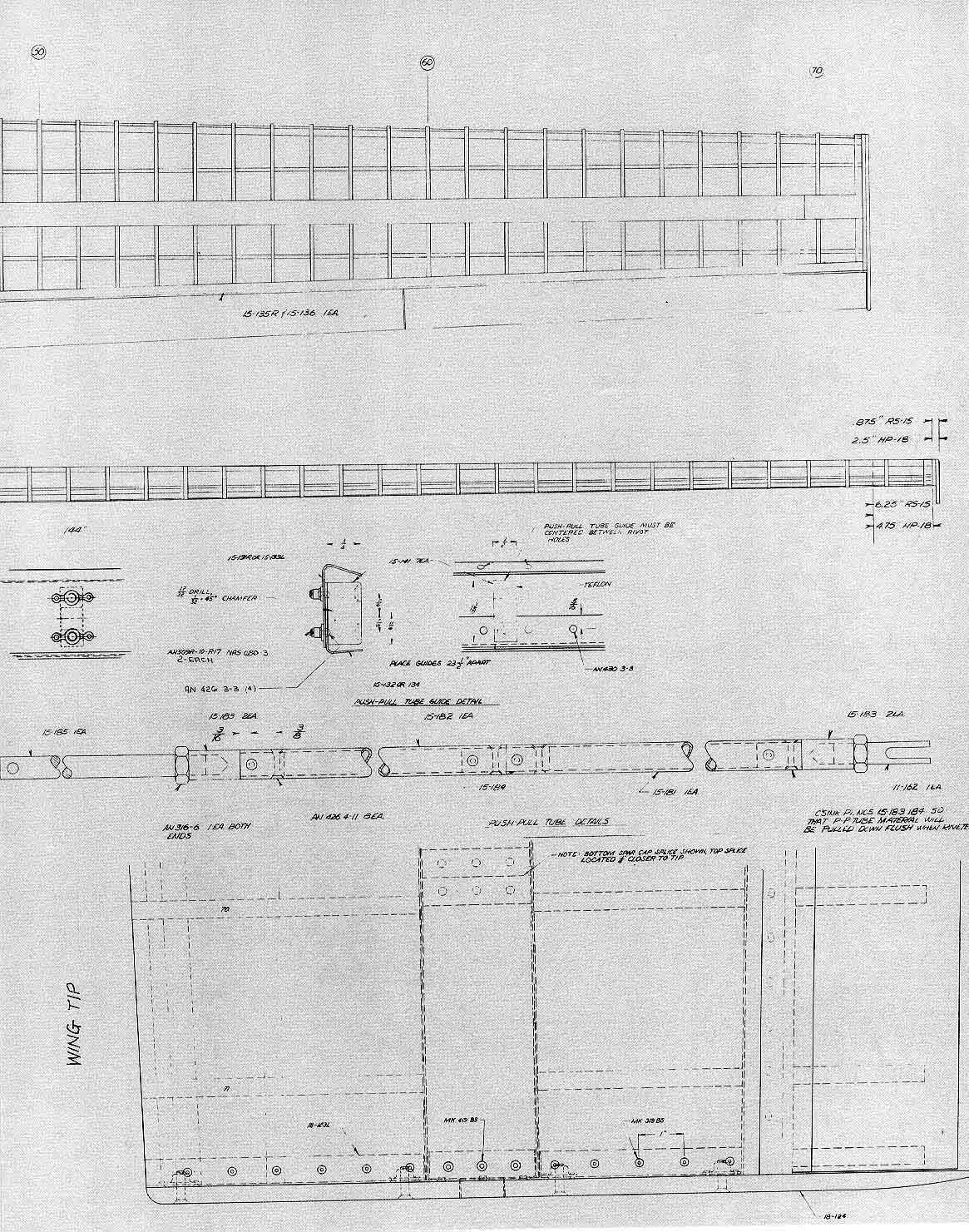
Other items such as wing-spar drag fittings, splice plates, bell-cranks, wing tip, etc. are traced onto the stock which the builder must cut. Flaps and ailerons are in four-foot sections and each of these is fitted with three extruded piano hinges which are included in the kit.
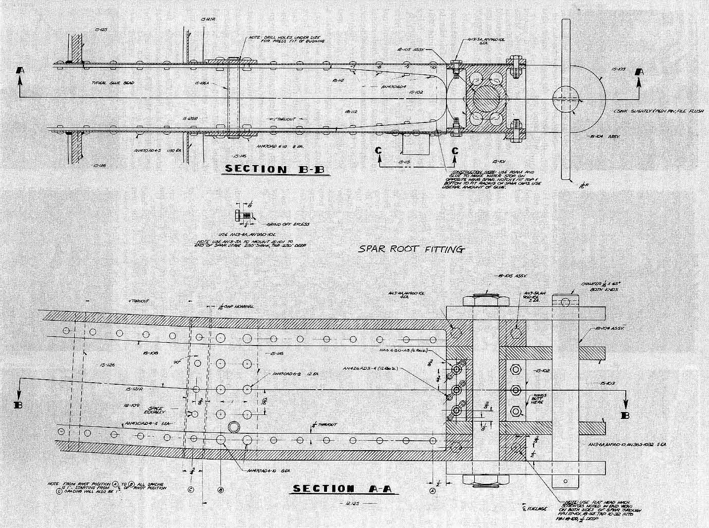
All of the necessary hardware such as rivets, bolts, nuts, washers, rod end bearings, cotter keys, etc. are furnished. A full-scale airfoil template, together with three upper and three lower airfoil contour templates, is supplied. The contour templates are used to ensure that there is no twist in the wing panels. The main spars each hold approximately 100 lbs. of water ballast. They are filled at the wing tip and dumped at the root into the wheel well. Since these spars consist of two machined channels and two shear webs which are riveted together, it is necessary to slosh them with a rubber sealing compound which comes with the kit.
When completely finished and painted, the wings- weigh 135 lbs. each. They mount on the fuselage with four pip pins in the drag fittings and two handle pins through the main spar. The wings are joined together with one I"-diameter vertical pin at the center. Flaps hook up automatically. Ailerons are connected to the fuselage control system with two bolts at the present time. Later we hope to replace the bolts with quick-disconnect fittings. The flap and aileron interconnect system is operated by a cam at the center of the fuselage. The advantage of the cam type interconnection is that any variety of motions may be incorporated by simply changing cam plates.
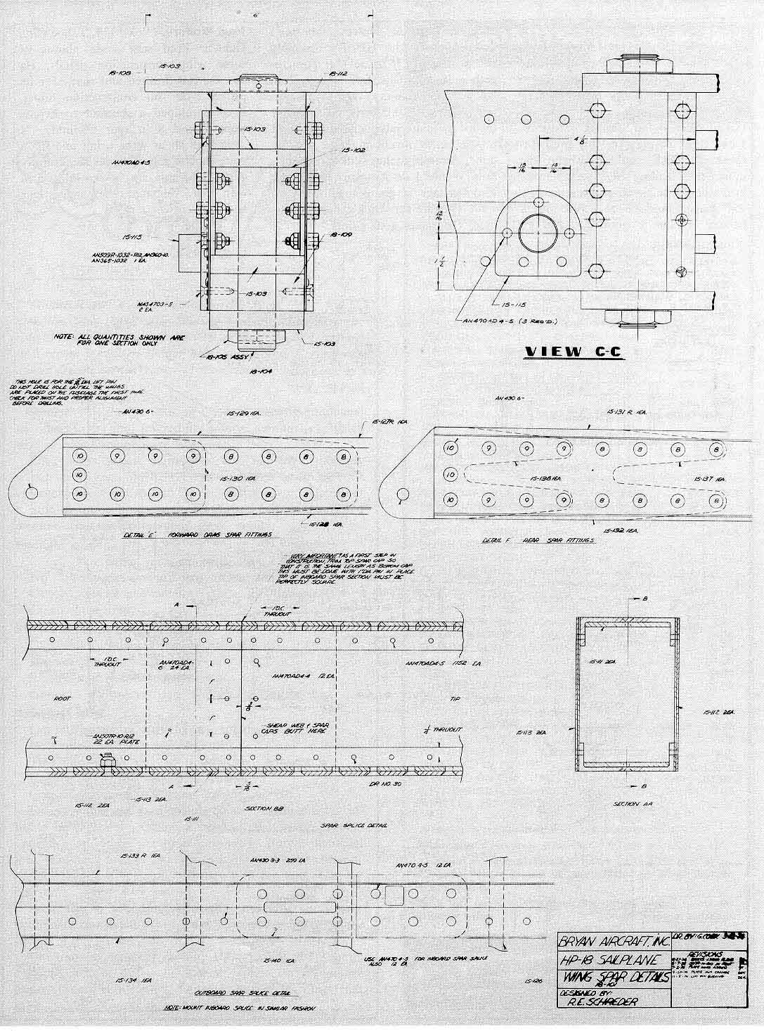
Let's begin with the spars. Here are thirty steps included in the kit instructions for assembling the main spars.
|
|
Building the spars:
1. File shear webs to scribed trim lines.
2. Examine spar caps and remove any deep scratches with file and emery cloth.
3. Cut, file, and fit spar splice-plates. Bottom edges at center of plates should be filed to fit cap flange radii.
4. Clamp inboard and outboard spar cap sections together with splice plates in place. Be sure that cap ends are together and that they form a straight line. Clamp a long straight bar against both sections to ensure alignment.
5. Drill caps and splice plates with a No. 30 drill guide and cleco together. Finish drilling (No. 13). Splice plate screws should be a light press fit.
6. Countersink spar cap holes with 100degree micrometer countersink so that special NAS 4703-5 screw heads fit flush on outside of spar caps.
7. Drill (No. 30) rivet holes in set of shear webs for one side of spar using drill guide. Make certain that you start at the hole that will be used for picking up the flange of No. 1 rib so that all holes will come in the same station on the finished spar. Drill remaining holes in root portion of web exactly as shown on drawing.
8. Use the first shear web set as a drill guide for the other three and stack drill (No. 30).
9. Clamp shear web to spar caps. Install 1" pin through caps with inside splice plates and spacer in place. Use a square on the cap ends to ensure that the root of the spar will be perfectly square. Adjust caps accordingly so that I"-dia. pin will fit freely. This will be the left main spar.
10. Drill (No. 30) through web holes and spar caps while holding edge of web on edge of cap.
|
|
11. Clamp shear web on opposite side of spar and repeat drilling process outlined in Step 10.
12. Drill through root spar cap spacers, spar stiffeners, and water dump-tube plate.
13. Drill (No. 12) holes for 10-32 through bolts and drill (No. 21) and tap blind holes for 10-32 screws.
14. Drill ballast drain holes in front side of inboard spar shear webs.
15. Temporarily install main-spar splice traps and outboard spar caps.
16. Drill outboard shear webs as outlined in Steps 7 and 8. Clamp them in place and drill as in steps IO and II.
17. Fit and drill tip extensions, cap, aileron bell-crank supports, and root and tip ribs. Be sure to make right and left wing panels.
18. Disassemble and clean all parts and spray with zinc chromate. Spar caps are 7075-T651 aluminum and will corrode if they are not protected. Omit paint from outside surface of caps and both sides of shear webs.
19. Reassemble caps and shear webs on one side. Rivet together.
20. Glue water-tank sealing foam bulkheads in place. Apply epoxy on edge for opposite shear web.
21. Cleco opposite side shear web in place. Start riveting at root. Bend outboard end of shear web away from spar so that you can reach inside to buck rivets. Buck both top and bottom rivets as web is laid down on spar. Be sure to get the proper rivet length in the ribs and bell-crank supports. After the tip rib has been riveted to the cap, it will be necessary to pop rivet the cap onto the end of the spar.
22. Some flat-head screws must be used as shown on drawing. Stiffeners must be countersunk 100 degrees to fit the heads of these screws.
23. Install all screws in spar root.
24. Replace 1"-dia. pin with 1"-dia. bolt and nuts in left main spar root. Mate right spar caps and spacer to this assembly and install 1"-dia. pin in right spar hole.
25. Repeat above steps in assembly of right spar.
26. As soon as inboard shear webs are attached to right wing root, main pin may be removed to separate spars.
27. Put a drop of epoxy glue on the head of each pop rivet to cover the stem hole.
28. Spars may now be sloshed with rubber sealing compound (supplied in kit). Mix a quart of thinner with the gallon of cement. Stir thoroughly and pour into spar with the aid of a small funnel. Be sure that there is a cork in the tip filier neck. After filling, install a second cork into the root dumping tube and rotate the spar several times with one end elevated, then repeat with other end elevated.
29. Remove cork from root and, with tip elevated, drain all sealer that will come out.
30. Pour remaining sealer into second spar and repeat process above. Make certain that sealer coats all surfaces inside spar. Drain sealing compound from this spar and store for later use in attaching Plexiglas to canopy frames.
|
|
Before getting into the assembly of ribs, spacers, and spars, I'd like to note some of the considerations that resulted in foam construction being used for the HP-18 ribs and spacers. We learned that plastic foam ribs have many advantages over conventional metal practice in amateur-built metal sailplane structures. They are simpler, faster to make, inexpensive, lighter, stronger, have a stiffer surface, and permit more accurate contours. Half a dozen in-flight encounters with rocks, trees, sagebrush, and a flagpole have proven that foam-ribbed structures can take more punishment with less damage and simpler repairs than conventional metal construction. Impact damage tends to be much more localized. The cells formed by the closely spaced (four-inch) ribs and span-wise spacers resist the formation of wrinkles beyond the actual area of contact that usually develops in ruptured metal components.
Torsional strength is greatly increased by the buckle-resistant support provided by the closely-spaced ribs. Further, an extremely smooth wing surface results from pressureless gluing of skins to the rib and spar structure. Skins that are bent over the supporting assembly fair out any depressions or unevenness and avoid distortions induced by extensive riveting.
Only PVC and acrylic foams are recommended for this type of construction because of their superior combination of high strength, moisture resistance, high temperature tolerances, and ease of fabrication. True, urethane is cheaper and more readily available, but it is not as stiff and tough as PVC and acrylic types.
Great variations exist in epoxy adhesives. Most are poor in peel strength. Some lose their grip under stress in high-humidity environments. Only one brand has been found to be entirely satisfactory for our foam-and-metal construction. It is Dexter Hysol EA9410.
|
|
Attaching the wing ribs:
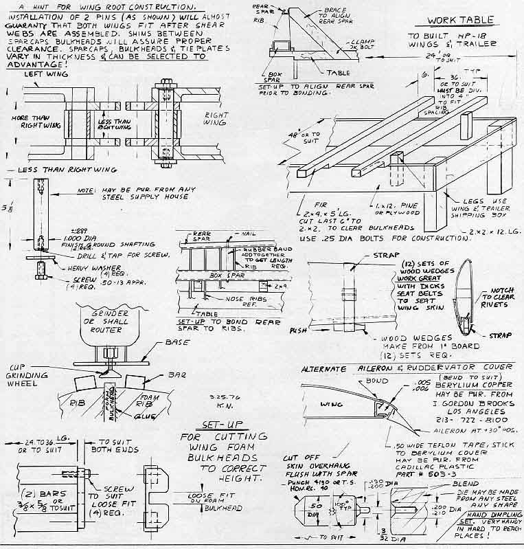
1. Cut five 3/4"x3 l/4"x36" boards and nail them across the top of your 2'x24' wing assembly table with 6" overhanging on each side. Spacing of these boards must match the rib spacing so that they will fit between ribs when the uncovered wing assemblies are placed on the overhanging ends. (The following instructions are for one wing but it is recommended that both wings be assembled at the same time to prevent loss of time while waiting for epoxy to set up on one wing.)
2. Lay the completed spars on the overhanging boards, one on each side of the table, with the root-and tip ribs oriented with the leading edges up. Use the root and tip rib templates to verify that there is no twist. This is accomplished by holding either the top templates or the bottom templates on the ribs and sighting the straight edges of the templates to make sure that they are in line.
3. Clean and scuff front shear web.
4. Mark positions of foam ribs on front spar shear web with ballpoint pen. Do not touch gluing areas with fingers.
5. Stretch a strong nylon thread from the leading edge of the metal root rib to the metal tip rib.
6. Apply epoxy to attaching edge of No. 2 nose rib and place in position on line. Leading edge of rib should be aligned on thread. Use square to ensure that rib forms 90-degree angle with spar.
7. Install a 2" length of 3/4" masking tape on top and bottom edges of rib at spar joint. These strips will hold the rib upright and prevent any shifting. If ribs do not match spar width precisely, split the difference at top and bottom equally.
8. Repeat steps 6 and 7 for remaining nose ribs. Leave in position until glue has set. Check 2 or 3 times to make sure that ribs do not slip out of position or tip over before glue sets.
|
Foam rib kit package. |
9. When epoxy has cured, wings should be rotated 180 degrees and rear shear web should be prepared as per Steps 3 and 4.
10. Stretch a thread from the bottom corner of the No. I metal rear root rib to the bottom corner of the rear metal tip rib.
11. Apply epoxy to attaching edge of No. 2 rear rib and place in position on line. Rear bottom edge of rib should be aligned on thread. Use a square to ensure that rib forms 90-degree angle with spar.
12. Use tape to hold ribs in position as in Step 7. If ribs do not match spar width precisely, split the difference at top and bottom equally.
13. Repeat Steps 12 and 13 for remaining rear ribs. Check frequently to make sure that ribs do not slip out of position before glue is set.
14. Rear ribs can be held in better alignment while glue is setting by laying some of the 3/8"x35/81' foam spacer board stock on the rear rib ends and pushing a straight-pin through the tip into each rib.
15. Assemble rear spars. Do not overdrive rivets as metal expansion will cause spars to curve.
16. Sight main spar to see that it does not sag and that it is perfectly straight.
17. Place rear spar on aft end of rear wing ribs. Spar should touch all ribs. If any foam ribs are too long, sand them -down as necessary. Occasional short ends up to 1/16' will be bridged properly when glue is applied. Sight rear spar to verify that the plane of shear web is straight.
18. Clamp rear spar to metal ribs. Both metal ribs must be exactly 90 degrees to the main spar. Make sure there is no twist in the ribs and that the rear spar flanges are in perfect alignment with the rib flanges.
19. Drill (No. 30) and cleco through rear spar and rear rib flanges.
20. Remove spar, clean, and scuff.
21. Apply epoxy to rear ends of foam ribs and replace spar. Cleco to metal ribs.
22. Tape ribs in place on rear spar to maintain 4" spacing. Check top and bottom rib edge surface alignment with rear spar flanges by using two straightedges. Split any variations equally. Check to verify that metal ribs are still 90 degrees to the main spar.
|
Metal tip rib is used with root rib to ensure alignment. |
23. Install aileron bell-crank, and make sure that bell-crank arm operates freely in the rear spar slot. Do not file out ends of slots until ailerons are mounted as the ends serve as bell-crank stops to limit aileron movement to specified up and down values.
24. Install aileron push/pull guides on aft side of rear spar. Make sure they are square with spar centerline.
25. Rotate wing 180 degrees.
26. Assemble forward drag spar.
27. Mark nose ribs 2-8. The length of the line on No. 8 should be the same as the outboard end spar depth. Cut off 2-7 nose ribs with a razor blade. Save pieces for reattachment after spar has been mounted.
28. Trim nose ribs 2-7 to accommodate drag spar flanges.
29. Clamp front drag spar assembly in place and drill rivet holes through spar and No. I rib flange.
30. Remove spar, clean out chips, clean and scuff, and glue assembly in place. A block of foam should be glued into the joint on No. 8 rib for additional support.
31. Trim, fit, and glue severed nose sections of ribs 2-7 in place in front side of drag spar. Make and install a No. I foam rib section.
32. Rotate wing assembly 90 degrees and place on table. Stretch a string from root to tip to mark positions of rib spacers as shown in the drawing. Use a razor blade or saw to cut I" foam strips into 3 5/8" lengths for leading edge spacers.
33. Glue I" spacers between the front ends of the nose ribs as shown on wing drawing. Do not allow length errors to build up and bend the ribs out of position. Use straight pins to hold spacers in position.
34. Cut sections from 3 5/8" boards to fit between ribs and form bulkheads. These pieces should be slightly longer than the rib height so that enough material extends above and below the wing surface to allow later sanding to airfoil contour.
35. Glue bulkheads in place as they are cut. Do not allow variations in width to build up and bend the ribs out of line.
36. After all bulkheads are in and the epoxy has set, sand top and bottom edges to match rib height. Use a 1 1/2 x 1 1/2 x l2" wood block with 60grit emery cloth contact-cemented to one edge. Extend the 1 1/2" strip of emery cloth around ends that are rounded to prevent snagging during sanding. Be careful not to cut into ribs. Final rib sanding should be done with a 11/2 x l l/2 x 48" straight wood block with 60-grit emery cloth attached as above. The ribs are slightly oversize to allow the removal of all high spots during sanding. There should be no flat spots and all curves should be smooth. No ribs should extend above or below the main spar shear webs. The flat area over the spar cap will be filled with epoxy when the skins are applied.
37. Check all ribs and foam spacers for glue drops and high spots. A long straightedge held span-wise across the ribs should touch all ribs. The sanding operation is very important as the skin must contact all ribs and span-wise spacers properly to ensure perfect skin fit.
|
|
|
Now it's time to skin the wing. By bonding instead of riveting the skin to the ribs, it is possible to give your glider an airfoil that is smooth and true if care is used in assembly. Flight tests show that two different copies of the same sailplane (even factory built) can vary greatly in performance because of seemingly small differences in accuracy and waviness of the skin surface and airfoil profile. To borrow an automotive figure of speech, it might be said that when it comes to getting the most performance, a sailplane's skin is "where the tire grips the road." There are 58 steps in skinning the HP-18 wing. Maybe there ought to be 59. Then the first step would read: "1. Use plenty of TLC."
Installing the wing skin:
1. Mark centerlines on front drag spar flanges for wing skin holes with a ballpoint pen.
2. Remove wing skin from crate by lifting at each end with a finger in leading-edge radius. Skins bent this flat will buckle very easily if they are not properly supported when lifted. They should be lifted at the radius at each end with a third person supporting part of the weight at the midpoint of the leading edge. Be very careful and follow this procedure religiously or you may destroy a wing skin.
3. Lay skin panel on a flat floor surface, covered with paper, with top side up. The rear edge of the inboard skin should rest about 6" above the floor at the root and 4" at the outboard corner. The outboard section should rest from 4" at the inboard end to 2" at the tip end. If the skins are not bent enough, they can be 'bent further, after laying a 2"x6"xl2' plank on top of the skin at the leading edge, with light springing of two normal-sized men who are standing on the plank.
4. Slip inboard section of skin, top side up, over wing panel which is supported on a 2"x4" block under the root section of the spar and another block under the spar just outboard of the end of the inboard wing skin. Use 3 or 4 people, if possible, to support the leading edge when the skin is slipped in place to prevent buckling. Such buckles are just about impossible to iron out and will result in cracks if they are severe. Let's do everything possible to avoid buckling!
5. Place fifteen 2" wide straps around wing assembly at 10" spacings.
6. Install 3/4 " x 3 1/2 " boards cut t o lengths that will fit between aileron push/pull guides on back of rear spar. The purpose of these boards is to apply force from the straps to push the wing assembly into the skin. Boards should extend at least I" aft of the rear skin edges.
7. Tighten straps to force nose ribs all the way into the leading edge radius of the skin. Extreme over tightening could crush some of the ribs. Light tapping on a 3/4" x 3 l/2" x 9" board held on the leading-edge radius will help seat the skin. A properly fitting skin will show a slight bulge at the leading edge where the nose ribs are pushing against the skin.
8. Check root rib and main spar for accurate 90-degree angle. Any error can be corrected by tapping front drag fitting in or out.
9. Place the root rib template and the No. 35 rib template in position and twist wing as necessary to get template straight edges to sight parallel.
10. Check rear spar and leading edge for straightness. Block and weight to hold wing straight.
11. Skin overhang on root rib should cover rib flanges with about 1/81, extra for good measure.
12. No gaps between wing and skin structure should exceed 1/32". If the skin is tight all the way around and there is no twist or sag in the rear spar, clamp the drill guide to the skin over the rear spar flange and drill (No. 41 ) the first hole so it will be on the rear spar rivet line where it intersects the root rib skin rivet line.
13. Drill (No. 41) holes through rear spar Ranges shifting drill guide outboard when all its holes have been used. Cleco every fourth or fifth hole as drill guide is moved. Use a 6' scale or metal strip held under the skin overhang against the rear spar flange to accurately measure the correct distance of the drill guide from the edge of the rear spar.
14. Drill (No. 41) holes through root rib flanges.
15. Drill (No. 41) holes through front drag spar. Use extreme care to find previously drawn spar Range centerline when each hole is drilled. A mistake here will result in a series of holes running off the edge of the spar.
|
Designer/builder/pilot Dick Schreder wearing his builder's hat. |
16. Re-drill (No. 35) front spar holes and splice plates.
17. Mark skin on inside surface by tracing around flange of root rib with a ballpoint pen. This line will indicate trim line after skin is removed.
18. Mark outboard end of skin for trimming midway between ribs 35 and 36. Use a straightedge that can be curved to fit the skin surface for this marking. Don't try to wrap the straightedge around the leading edge as the trim line must lie in a vertical plane midway between the two foam ribs.
19. Lay out inboard skin splice hole patterns on skin, fit and clamp splice plates in place and drill (No. 41).
20. Turn wing over and recheck for twist and straightness. This is the last chance you have to assemble the wing without twist or bows in the leading edge, main spar, and rear spar. Make certain that everything is exactly right before any holes are drilled in bottom skin surface. Drill bottom side as in steps 12-18.
21. Trim bottom skin to edge of rear spar. Stretch a string to mark skin properly and ensure that trim line is perfectly straight. File as necessary.
22 Clamp flap hinges in position and drill (No. 41). Make sure that all hinge sections are in a straight line by using a straightedge.
23. Remove skins, clean out chips, and trim inboard and outboard ends.
24. Countersink all rivet holes in front and rear spars, No. I root rib, and skin splice plates.
25. Dimple skin holes.
26. File 3/16"-deep notches in the bottom edge of all foam ribs with a 1/4" round file just forward of span-wise stiffeners ahead of main spar and just aft of span-wise stiffeners in ribs behind main spar. Consult wing drawing for locations. These holes are necessary to drain moisture and relieve pressures inside the wing. Be sure that all compartments are so vented. Serious structural damage will result if any space remains sealed. Punch holes in 1" spar strips between nose ribs with an ice pick.
27. Clean and scuff wing skin, spars, and metal ribs.
28. Make preparations to glue skin to wing structure. Consult page 35 in the April Soaring for method of mixing glue, quantities of glue necessary, and method of application. Measure amount of glue required in batches of 8 oz. each and necessary hardener for each batch in separate cups. A minimum of four people will be required for the mixing and gluing operation. Glue batches should be mixed just prior to the time of application and should be poured immediately into the dispensing envelopes. Application should proceed immediately as such large quantities of epoxy will harden very rapidly due to exothermic reaction.
29. Snip the tip of the applicating envelope off where it is 1/4" wide. Squeeze bag and lay down a 3/16"dia. strip of epoxy on the edge of each rib, spacers, and front drag spar on bottom side of wing only. Put 2 or 3 rows on the main spar. Don't try to skimp on the amount of glue as too much is better than too little. Spread glue out on main spar to cover the entire surface so that no bare spots are left for corrosion to develop. There must be enough glue to fill the small space between the skin contour and the flat cap surface.
30. Replace wing skin and cleco with bottom side up. Skin should be snug against spar and ribs. Apply epoxy to outboard splice plates and cleco in place. Hand pressure on skin over ribs and spars will help the glue flow under the skin. Straps and/or boards are not necessary or desirable. If skin tends to gap away from ribs just aft of leading edge, lay a series of aluminum or steel bars on the wing surface in this area ahead of the main spar. Bars should be approximately 1/2" square x 12' long. Do not use short pieces of bar or various weights to solve this problem as a very uneven wing surface will result. Wing must be properly supported if such weights are added.
|
|
31. Pop rivet front drag spar and splice plates.
32. Rivet end rib and rear spar. Don't forget to attach flap and aileron hinge as shown on wing drawing.
33. After glue has set at least 12 hours, turn wing over and carefully lift top skin to examine interior for completeness of glue job. If any ribs or bulkheads are not glued securely to the skin, lay an additional bead of epoxy along such ribs and bulkheads.
34. Repeat steps 28-31 for gluing top skin to structure. More epoxy will be required on the top of the main spar than on the bottom because of the larger space between the more highly curved skin and the flat spar surface.
35. Do not trim aft edge of top skin until flaps and ailerons have been installed.
36. Install outboard wing skin, top side up, with inboard end on splice plate and as close as possible to the inboard skin without overlapping.
37. Reuse skin straps and rear spar boards as in Steps 5-7. Remove twist by using midpoint and tip templates.
38. Check rear spar and main spar for straightness and sag-free alignment for entire length of wing panel.
39. Check leading edge for straightness and proper contour match by stretching a string from root to tip.
40. Measure maximum chord-wise skin gap at junction of inboard and outboard skins.
41. Cut strip of thin metal to width of maximum gap measured and use it as a gauge to mark a uniformly spaced line from the inboard skin onto the outboard skin.
42. Loosen straps, trim skin, replace, re-strap and recheck for straightness and lack of twist. Joint should fit perfectly. A gap of 1/16" would be acceptable as such variations can be filled when the wing is painted. File to fit if necessary.
43. Lay out holes in splice plate area and drill (No. 41 then No. 35).
44. Drill rear spar (No. 41) and wing tip rib holes.
45. Mark inside of skin around tip rib.
46. Turn wing over. This is the last chance you have to assemble the outboard section without twist or bows in the leading edge, main spar, and rear spar. Make certain that everything is exactly right before any holes are drilled in bottom skin surface.
47. Repeat Steps 43 and 44.
48. Trim skin as in Step 21.
49. Clamp flap and aileron hinges in position and drill (No. 41). Make sure that all hinge sections are in a straight line by using a straightedge.
50. Remove skin, clean out chips, and trim outboard end.
51. Fit wing skid to tip rib, drill attaching holes, and install anchor nuts inside tip rib.
52. Countersink all rivet holes in rear spar, splice plate, and tip rib.
53. Dimple skin holes.
54. Clean and scuff wing skin, spars, and metal ribs.
55. Reinstall skin and repeat gluing procedure used on inboard skin, Steps 28-33.
56. Repeat Steps 28-31 for gluing top skin to structure.
57. Install tip skid plate and sand to fit outer skin contour.
58. Cut stainless steel hinge pin stock to length by notching with a triangular file and bending to break. Bend 1/2" 90 degrees at one end. Taper straight end by rotating pin against grinder wheel or belt sander.
Next month we'll cover the 26 steps it takes to assemble the HP-18's flaps and ailerons as well as covering the I I steps needed to finish the wing surfaces. See you then.
|
Blue Prints (file size about 200k) |
|||||
FROM THE BUILDERS
Konrad Nierich (Costa Mesa, Calif.): "Here are a few sketches that may help other builders of the HP-18. Having completed the trailer, wings, flaps, tail, tail-cone, and having installed most of the fuselage hardware, I can think of only one big improvement: If Dick could pre-shape the upper skin leading edge, many man-hours could be saved and a truer airfoil shape could have been achieved. But I believe he has a good kit and an excellent sailplane. However Soaring's description of the HP-18's assembly in the August '75 issue ("It goes together like a Christmas bike from Sears") made me cry. Who ever heard of a bike with 10,000 rivets? Basically the kit is a materials package with most of the heavy machining and welding done. Assembly takes skill and dedication. Would I do it again? Definitely. The fuselage is going together quite well. Hurrah for Dick's new draftsman! He makes good prints."
Fred Wofford, (Tahoe City, Calif.): Fred sent some photos of some wing construction details. He has the tail finished and ready for its primer after 60 construction hours. Fred developed a shortcut to bypass steps 7 and 8 -in spar assembly. "I drilled all shear webs-using one for a pattern. Use a hole finder to carefully align the spar cap holes. Pilot drill with #41." He has other suggestions and will answer letters.
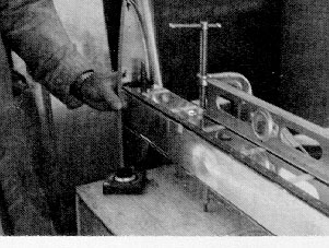
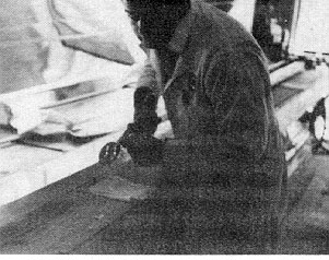 Homebuilder Fred Wofford fitting spar web to cap strip.
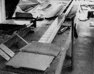 Spar with one shear web in place. Wofford has used materials package for work bench.
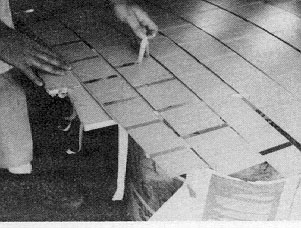 Removing masking tape after spraying spar web. PVC ribs bond to the unpainted material.
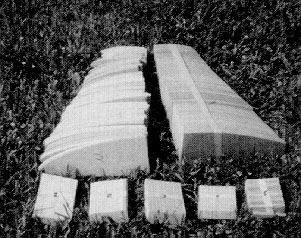
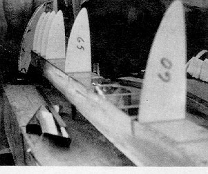 "Wonder how it'll look when I put it together?" A temporary pre-assembly fitting.
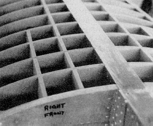 Structural muscle: When metal skin is bonded to ribs and massive metal spar the result is a cellular structure of great strength.
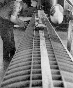
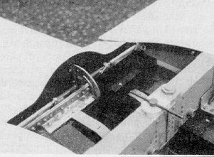 Spar union and attach assembly. Note water ballast dump tubes. Mixer and aileron/Rap interconnect will be detailed in future installment.
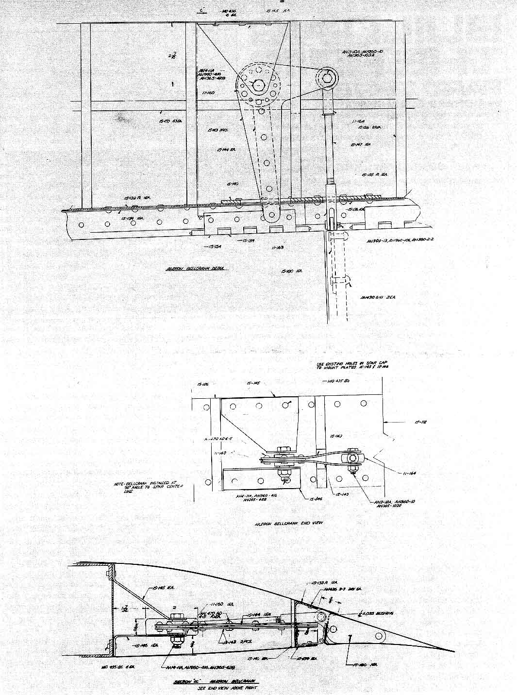