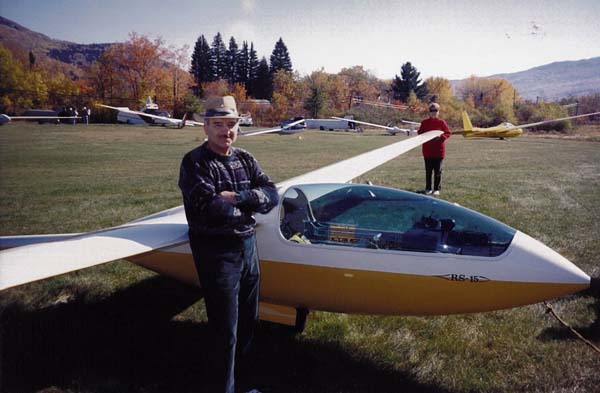
N15BL is serial number 32, and was built by a mechanically gifted and very meticulous experienced pilot, who also happened to be a math teacher (now retired) from Bennington, VT - Larry Hager. Larry's wife's name is Bev, hence the "BL" in N15BL. After flying "BL" for a couple of years, he made a decision to sell his work of art. He then spent the next five years waiting for that person who was as persnickety (or perfectionist, your choice, my wife has her own opinion about the two of us) as he is. I was the lucky one.
My first flight in "BL" lasted 2 hrs 10 mins, my second the same day for 5 hrs 5 mins. I have since made many flights over 5 hrs. one over 6-1/2 hrs, flown it to 25,000 ft over Mt Washington, NH, and made several solo cross-country flights. However, therein lies my reason for selling "BL". While it is a pleasure to fly, a great thermaler, and a comfortable cross-country bird with a roomy cockpit, it cannot run with or compete reasonably with the glass ships. Most of our club members have glass ships, so I am attempting to join the crowd. Having competed for many years in the Air Force to become an experimental test pilot, and then being fortunate enough to perform as such for seven years, I thought my need to compete was behind me, but taint so, so another reason for moving to higher performance.
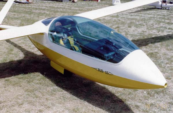
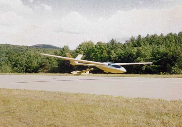
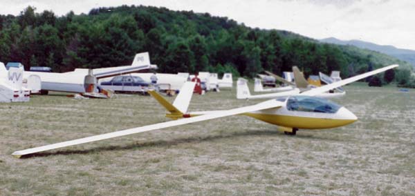
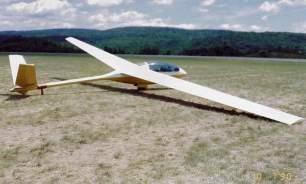
The first four pictures were taken at Hartness State Airport in Springfield, VT where our club has its annual two-week soaring encampment. The 5th picture was taken at Gorham Airport, NH where I made the 25K flight over Mt Washington 10 miles away.
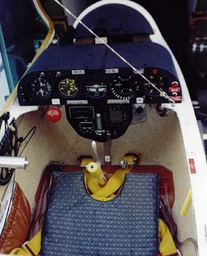
T'he next five pictures are photos of the cockpit as you requested. As you can see, Larry built the standard Schreder sill-to-sill instrument panel. He had slung a 10 channel Genave under the panel with a 3 1/2" clock next to it. In the panel he only had four instruments: Altimeter Air Speed indicator, Netto Vario and a Cambridge Audio-Vario, with a plate covering the center cutout.
The first addition I made was an electrical turn-and-bank in the center cut-out, which is switched on as needed by the inboard of the two lever switches at the top left of the panel. This switch in turn can only be powered when the outboard of the two toggles, or master power switch, is flipped inboard to the on position. Between the two switches is a low-voltage LED that lights when the master power switch is flipped on, giving an immediate indication that the ship's battery is correctly installed. |
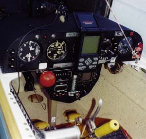
I constructed the fully enclosed, tapered sub-panel, which I designed to conform to the mold line of the aircraft to allow unrestricted leg access. I then installed a TX-720 radio, an M-Nav computer, an electrically powered chronograph, and the flow gage and controls for the oxygen system that I also installed in the aircraft. I replaced the Audio-Vario with the M-Nav Vario. On the top right side of the panel is a push-to-test switch and gage to test the battery power level. On the right side of the panel are two red warning lights that indicate respectively, with battery power on, canopy unlocked at any time, and gear up with flaps extended for landing (30 degrees or more). A warning horn is also activated when the gear warning light goes on. |
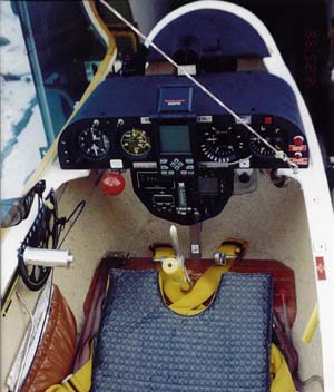
I solved the GPS problem by installing a LowRance unit using Velcro strips. It mounts over the turn-and-bank, an emergency instrument normally, and can be removed quickly in- flight if inadvertent cloud entry or flight into heavy precipitation occurs. It is powered off the ship's battery through a shielded coaxial cable that can be pulled out of the panel as needed. |
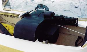
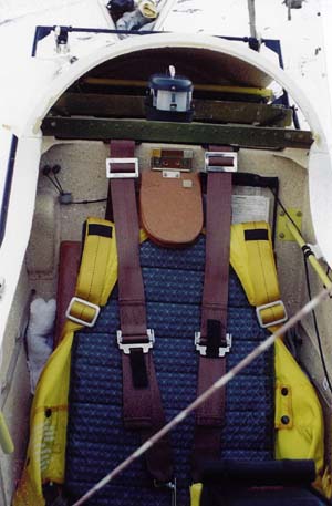
The picture shows the two turn point cameras that I installed forward of the instrument panel and remote from the pilot. They are activated simultaneously by a remote pneumatic (camera) squeeze bulb resting in the pilot's lap. |
This photo shows the location I chose for the Replogle barograph, attached to the battery compartment lid behind the lay down headrest. Beneath the battery compartment is the landing gear box. There are cavities on either side of and between the gear box and outer skin. I installed the oxygen supply bottle in one, and a drinking water supply in the other, with the water supply tube running along the right side of the cockpit up to the right knee area. The oxygen supply line runs under the cockpit and rises to the instrument panel through the square tube shown below the panel. |
|