Wing Transporter
LWT-3
By Ralph Luebke
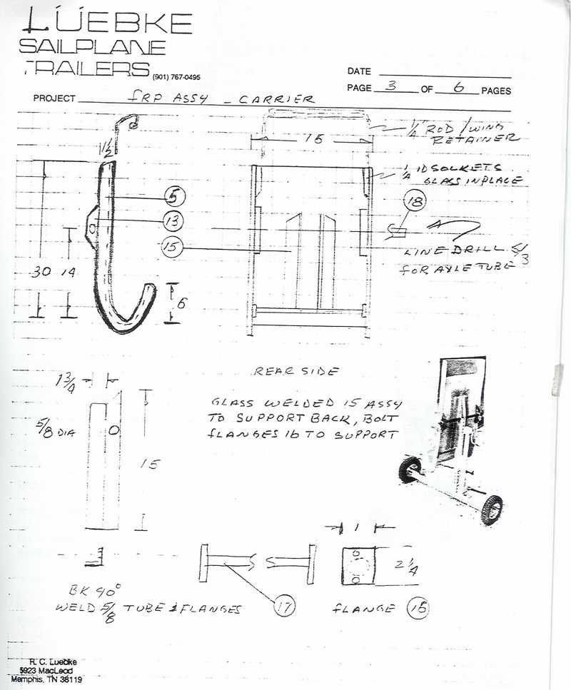
Sailplane Builder (May-June 2002)- Pages 24-28I received the following article and drawings from Ralph, including this note: "Finally found time to review my shop notes and finish some sketches of the wing transporter. LWT-3. This represents one of a series that we built and used for some years. The carrier (5) may be made of aluminum or FRP with a foam core. A rubber lined aluminum carrier works well if you use the carrier for a variety of wing size, such as the fat wing of the Grob Twin series through the latest 15M series. If you want a customized fit -- a layup of four layers of 8 oz. Glass, at the spoiler area, to form the J shape for your wing will start the process. Then trim and add 1/4 inch brown foam and 4 more layers of glass. At this stage, add a layer at the edges to form flanges that are required to stabilize the carrier. Glass in ½ inch hexcell hinge supports (13) just above the longitudinal CG of the wing location. After glassing in the center hinge assembly (15), apply the felt liner. This system should help your crewing chores. If you make the major pieces joint fits on the loose, the assembly will be easy to break down, for transport. "
Wing transporters, like other devices, are a design compromise. Include all the bells and whistles-the cost, weight and ease of use goes up. This unit is a simple lightweight design that will handle any wing weight, then stores easily for transport.
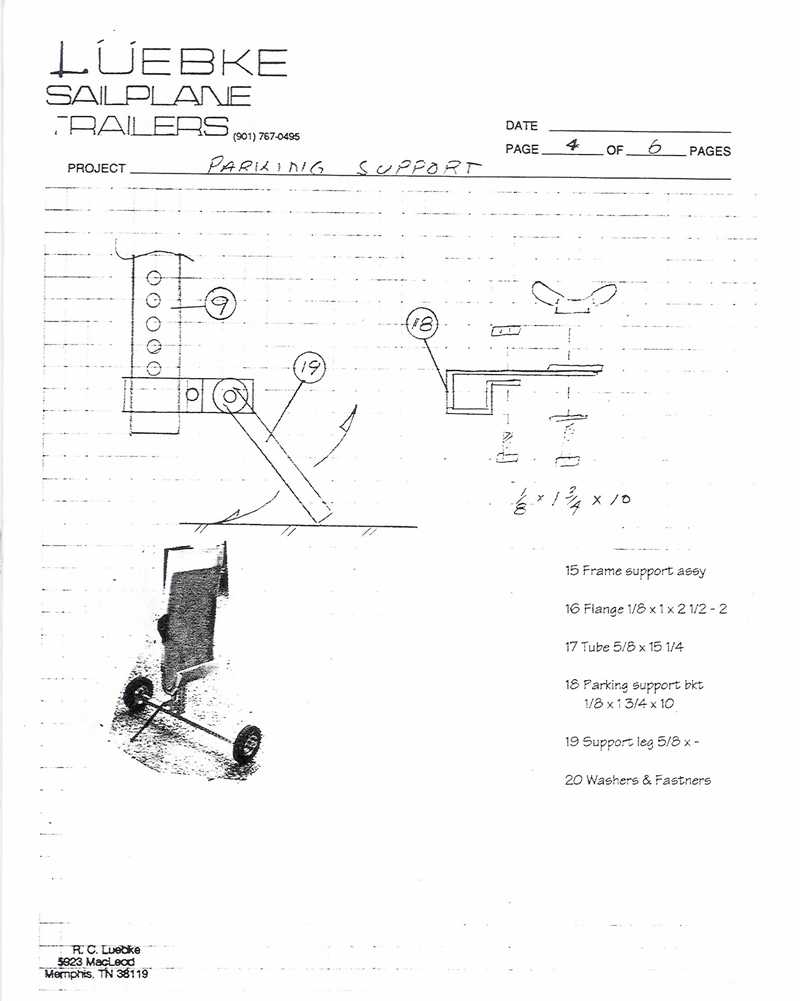
The carrier (5) may be constructed from either aluminum or FRP. A general-purpose rig, one that will handle a variety of wing sections is easily fabricated of aluminum. Make the J section large enough for the Grob Twin and it will accommodate most of the rest of the fleet. If you desire a custom fit for your ASC Spirit Ventus or similar, an FRP section molded with the use of your wing will result in a snug fit and a smaller size. Replicate the wing area at the spoiler to make a carrier (5). The sockets (13) are set just above the wing longitudinal CG. The jack (6) and carrier (5) are held in the sockets with quick pins. The carrier is dissembled from the jack assembly by removing the hinge pin.
Drawing A
Drawing B
Drawing C
Drawing DWayne Paul - Notes: After building a "transporter" base on this design I found that the jack crank interfered with the side of the fuselage. Udo Rumpf's "Wing Dolly" design has solved the problem. In this picture you can see that the jack is shifted 90 degrees. You will notice the location change by comparing picture Carrier 8 with Carrier 9.
Construction progress photos:
Carrier 1 Carrier 2 Carrier 3 Carrier 4 Carrier 5 Carrier 6 Carrier 7 Carrier 8 Carrier 9 Carrier 10 Carrier 11The 10 inch wheels can be purchased from "Harbor Freight" for $9.99 US (or $4.99 when they are on sale.) You can also save money at the automotive junk yard if you purchase a Ugo, VW, etc. jack instead of a Mercedes jack. (I found that the Ugo jack was the least expensive.) The glass lay-up is six layers of 22 oz knitted triaxial - bias e-glass. (It was left over from another project.) The glass lay-up adds a lot of weight. I ran out of felt. That is the reason for the gap in picture 10. The felt is self-adhesive polyester purchased from McMaster-Carr. The adjustment form a "C" clamp was used in the wing restraint. (Picture 11.)