Spar Riveting Tool
By Bob Kuykendall
|
|
|
|
|
|
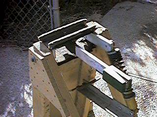
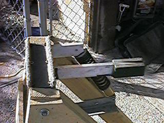
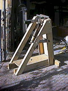
As you can see, the device consists of:
1. "A" frame that supports the other subassemblies. The frame is made of 2x4s and pieces of ¾" fiberboard. In the drawing, the frame assembly is shown in blue.
2. The anvil assembly, which consists of an arm that supports two bucking bars, (one for the top cap, and one for the bottom cap), a transverse support that suspends the arm in the center of the frame (made from piece of steel channel), and two pivot brackets that attach the transverse support to the frame. The pivot brackets were made of aluminum bar, and the upper shock absorber mount is built into the one of the pivot brackets. In the drawing, the anvil assembly is shown in red.
3. The table assembly, which hangs from the same pivot as the anvil assembly. The table assembly supports the wing spar while it is being riveted. In the drawing, the table assembly is shown in black.
4. The shock absorber assembly, which consists of a good 13" Bilstein shock absorber and spring from a racing motorcycle, and a lower mounting bar which adjusts the height of the anvil assembly by indexing to any of several holes. In the drawing, the shock absorber assembly is shown in black.
Also shown is a sample wing spar section. In the drawing, the spar section is shown in green.
NOTE: This drawing is not to be mistaken for a blueprint - I generally do a lot better when I suspect that a drawing is going into public circulation. It is provided as a courtesy to viewers.