A One-man Assembly Rig for the HP-18
By Hugh Helmick
Having flown the HP-11A for years with a simple one-man assembly rig, the need for assembly of my HP-18 was very apparent. It is really a big advantage to be able to stay airborne after other folks who could help with disassembly have left the field, and similarly, early assembly, prior to arrival of help is nice, in that the work gets done in the cool part of the morning. Problem with the HP-18 was that the wing seems considerably heavier than that of the HP-11, and its placement on the fuselage of the HP-18 requires great precision, in order to avoid gouging the fuselage brackets. It seemed that a counter-balanced dolly wing handler could do the job, and would be more precise and safer than a helper-person. Results with the system developed have been very satisfactory in these regards, and it rig even works safely in moderate winds. It generally takes me about 35 minutes from trailer through tape, working at a leisurely rate.
The design arrived at includes the following:
a. A padded cuff for each of the wings assists in support of the wings when in transiting into and out of the trailer. These are just outboard of wing (span-wise) center of gravity and when engaged to the support dolly, provide the second purpose of supporting the wings during lift, rotation and movement to the fuselage. One is on each wing, during trailering. This reduces fiddling during assembly.
b. An adjustable support dolly allows convenient adjustment of height and fore-aft positioning of each wing to get them really precisely located. This dolly stores in the aft end of the trailer while going down the road! It has a really wide wheel-base, for great stability. A wing support strut is attached to the dolly for convenient installation to support of the first (left) wing while the dolly is removed to go install the other wing. Go-cart tires provide great stability and roll easily in case of soft ground conditions.
c. A single wing-tip support stand is used to support each wing tip during the period between manual extraction of the wings from the trailer, until the dolly can be brought into play. This also is stored inside the aft end of the trailer.
This setup was built using hand tools, mild steel tubing and common brazing, and some minor riveting. Probably many soaring fans can duplicate the results, and may even suggest additional improvements. The scheme can obviously be adapted to other sailplanes. We've built a system like this for our ASK-21, and it is still feasible to one-man rig that big machine! I'd be glad to hear of any further ideas out there, and will field questions by E-mail. Contact me at
n413h@iwvisp.com, or the FindMail: hp-gliders. For those seriously interested, I can provide a video of the design features, and its use, for little more than tape and postage costs.An earlier modification to the trailer tailgate provides for smooth transit of the fuselage dolly off of the tailgate onto the ground. This isn't necessary to the assembly process if you assemble on the tailgate, but has proven to be a real convenience during maintenance, etc. Also made was a lever tool to gently but firmly bring the wing splice fittings together, and push them apart. These will be seen in some of the following images. Captions with pictures will hopefully add the detail and explanations as needed. No drawings are available at this time. If interest warrants, I might make up some shop-level sketches for posting on the web.
Photo credits: Steve Benson
All photos at Sierra Soaring, Inyokern Airport, CA
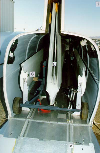
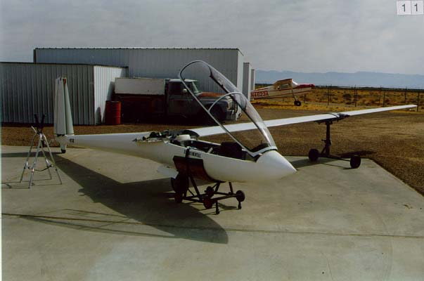
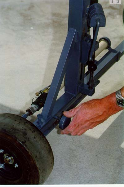
As seen opening the trailer: Dolly wheels fit between the tailgate, and the wing tip supports. Dolly is held down by the red strap and buckle. The high tailwheel on this HP-18 gives enough clearance for the cross-beam of the dolly under tail-cone. Seven inches is required, mine has 9 inches. The wheels are 4.10/3.50x4 go-cart hardware. The unseen lift pin toward the floor goes through a hole in the trailer floor. Putting my right foot on the dolly cross-beam near the red strap precludes any contact with the airplane as the dolly is rotated aft, and then rolled away from the trailer. Wing tip support stand is folded, and stowed on the right, with the legs pinched together, with one web of the track in between, and secured with hook and line to right tip support. Gliders with smaller original tailwheels could use a small support to elevate the tail in trailered position, since some height is generally available at the top of the trailer "doghouse". Note tailgate extension is in stowed position and pinned as shown (A). The tail vertical support is apparent here (B). The padded arm (C) assures wing can't be rotated excessively trailing-edge down, as it's being put on the fuselage.
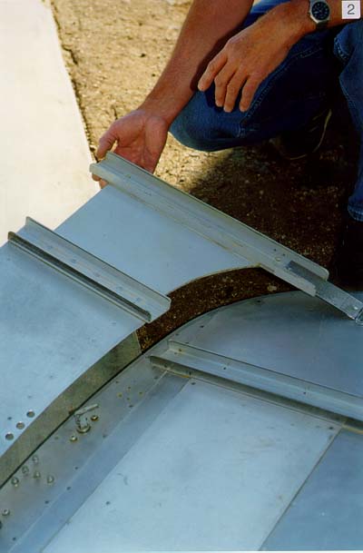
The tailgate extension fits entirely within the trailer when the tailgate is closed. Partially flexible, the hinge strips are skewed so the tracks will mesh when stowed (saves space), and align properly when extended.
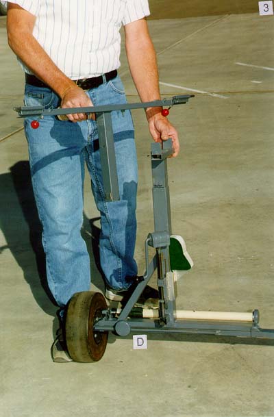
The dolly vertical support is three tightly telescoping pieces of square tubing. The innermost one is free to slide upward and even can be removed. This is handy in the removal of the dolly from under the wings after installation. The square tubes are closely shimmed in order to transfer twist/rotation from the wing being transported, to accurately steer the wheels. It can be seen that the bottom tee (D) can slide across the main support axle, between the wheels. This motion is closely adjusted by a rack and pinion. These are made by Boston Gear, and may be available through your bearings store, or through McMaster-Carr supply Company. The elevation jack hardware is commonly found in junk yards and is a "Fiat" tire-changing jack.
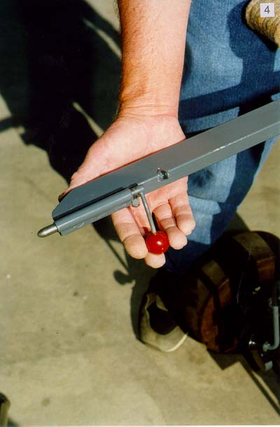
Close-up of one of the two retracting lift pins. They are locked in place by rotation of the handle against a screw with nylon button available from hardware stores. You DON'T want the pins to retract, except when called for! They're 3/8-inch steel, and tubing, and 3/16 handles, brazed.
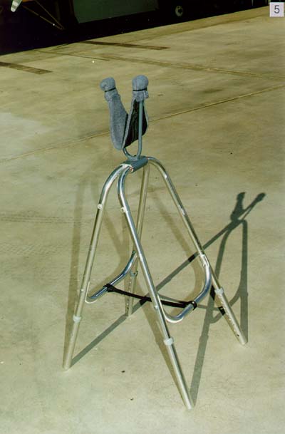
The wing tip support: Made from a "walker" from the thrift store. Two U-shaped pieces of 4130 with nylon shims firmly grip the two leg sets, which are button-adjustable for height. Steel U-shapes are screwed firmly to one pair of legs. Nylon limit strap sewn between. Very stable, and light.
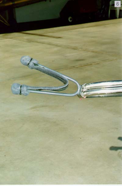
Red bushings and screws maintain lateral alignment of the leg pair that is free to rotate. Padding is supported by sewn nylon seat belt webbing.
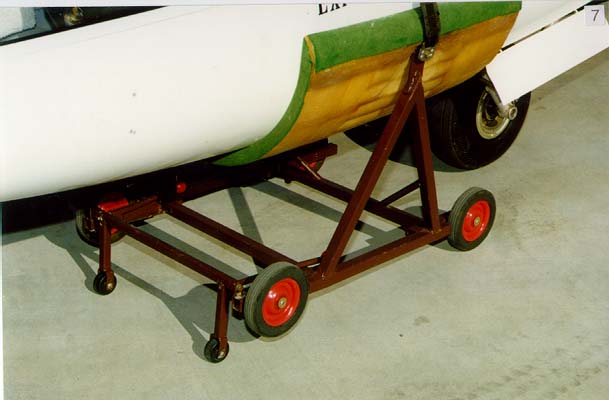
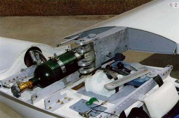
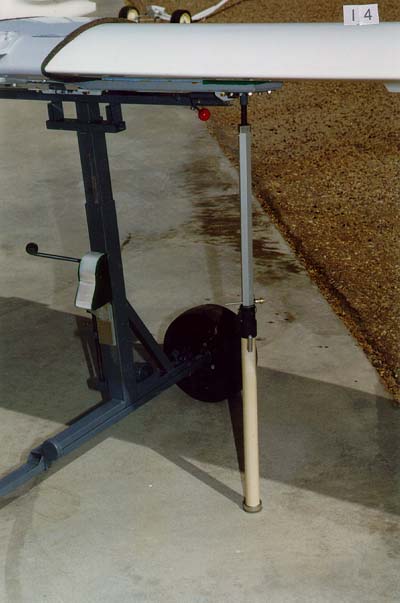
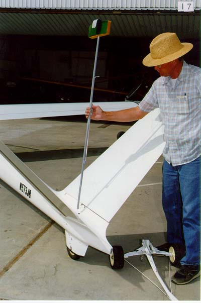
Although not necessary to the one-man assembly, this view shows means of elevating the dolly for gear extension, and lowering the glider on the main wheel. Handy for maintenance, too. Easy to lift the whole plane.
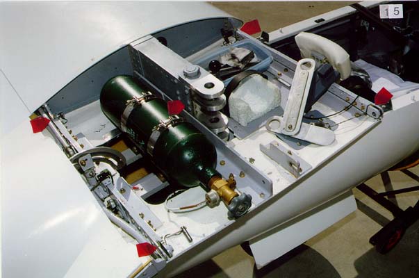
Wing cuffs as carried in trailer: Note that the left wing, which gets installed first, has a socket for the wing stand support strut, so the dolly can be used to the install the other wing. Socket is canted inboard and aft, to compensate for dihedral, and tailwheel perch angle, so strut remains vertical in its support of the left wing. Cam-Locks at trailing edge allows cuff removal from wing.
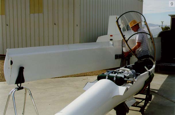
Installation of the support-dolly. Note that the tailgate is now level, held up by a folding support, in order to gain height at the wing root. When bearing the wing on the dolly, I have about 15 pounds of weight to carry at the root end of the wing.
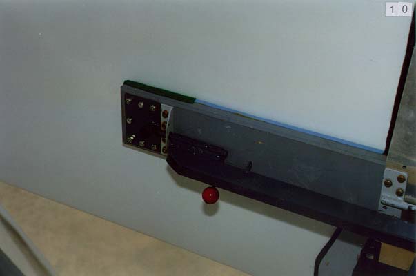
Detail of one of the support pins in place.
Getting there: Note that the tails are still securely supported vertically, and out of harm's way.
The Wing spars are initially supported on a wood block, to assess the alignment before setting down. Note wing pull tool in right foreground. Balls on spar lift pins help avoid dings to the hands.
Rack and pinion (fore-aft) and (up-down) jack are easily adjusted from trailing edge position of either wing. Wing support strut is seen secured on other side of dolly, where it is handy for use. Inner square tube is raised/lowered via through-bolts running in a slot seen in the outer tube.
Support strut in place: Made from professional painters' roller extension handle, at most hardware stores. These have a nice spring loaded locking pin and button, but pip pin is desirable safety backup! Bottom end has nested engine freeze plugs with pivot bolt and washer between, and rubber underside. It must not wander from vertical as it is twisted to adjust height. Fine height adjustment is by more "Fiat" jack parts. Other alternative supports would seem to require more storage and "run and fetch" considerations. So far, it works fine.
Inked lines in five places, with a little clear epoxy brushed over them assist in seeing any misalignment. Put them on sometime when you've got all the work done, and they'll save a lot of work on other days!
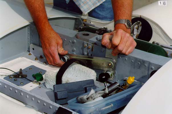
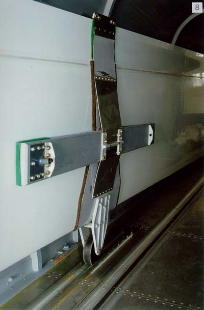
Pulling the wings together: I don't carry water, and just pull on the water fittings - similar thing could be done using some of the bolts in the spars, with spacers, etc. Tool has holes lined with continuous nylon grommet material, available from Small Parts, Inc.. This is a great mail-order source for materials, parts, and tools (
http://www.smallparts.com).
Removal of the tail support. Slip-fit socket tube is glassed into the tailcone, at a forward cant angle, placing the holder up at the top end of the hinge line, when tails are folded. MAKE SURE SOCKET TUBE CANNOT FOUL TAIL CONTROLS! Bottom two feet of the support tube are filled with a solid aluminum rod for rigidity in winds. It's also a handy place for storing the tail-mounted T-E probe. The tail dolly seen here was made form conduit and a leaf from a car spring. We pull our gliders to the runway with this, using a Honda ATV. Close-up of one of the two retracting lift pins.