I've just finished reading Hugh Gardner's article on designing and building a forward-hinge canopy system for his HP-18 project. I'm really impressed with the design and execution of his system. He went to a lot of trouble to make it clean and elegant, and it really shows. Having read what Hugh and Udo Rumpf and others have gone through, I'd like to add my own few thoughts on the matter.
First off, I'd like to introduce what I call the no-pivot zone. This is the area where it is difficult to place a canopy hinge pivot because of interference between the canopy and the fuselage during opening. Mind you, that isn't to say that you can't put a pivot in the no-pivot zone. Hugh and Udo's hinge systems both put pivots in the no-pivot zone, and get around the interference problem in different (and rather elegant) manners. It's just that it does make it a bit more difficult to make everything work out.
The no-pivot zone is defined by the angle of the surface on the fuselage that mates to the forward canopy bow. Looking from the side, and measuring from the high point on the line of the forward canopy bow, anything within 90 degrees of the bow is in the no-pivot zone.

As you can see in Figure 1, the no-pivot zone of the stock HP-18 leaves almost no place to put a pivot without interference problems.
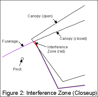
What happens when you put a pivot in the no-pivot zone without appropriate precautions? Simply put, the canopy and fuselage bump into each other in what I call the Interference Zone. The Interference Zone is where the fuselage and canopy try to be in the same place at the same time. This is shown in figure 2.

There are at least four ways I have thought of, and certainly many ways I haven't, to get around the interference problem with pivots in the no-pivot zone. It is important to remember that my diagrams here are simplified two-dimensional drawings of what is actually a three-dimensional problem.
Method 1 of getting around the interference problem is just to leave out the affected portion of fuselage, and have a gap between the canopy and fuselage in that area. For a sports car or powered airplane, this would be the preferable solution. Look around, and you'll see this a lot on car doors and similar situations. For a sailplane, however, and especially for the forward 20% of a sailplane, this just doesn't fly. Even in the positive pressure gradient of the nose area, this would certainly trip the boundary layer over the canopy, resulting in turbulent flow and lots of drag.
Method 2 is to very carefully shape the fuselage and canopy frame so that they don't actually meet in the interference zone, they just look like they do in side view. This being a three-dimensional problem, you can play with the surfaces involved to keep them out of each other's way. I think that this is the solution that Udo Rumpf went with, and it looks like it's also been implemented on at least a couple of German fiberglass ships. It's a real sleight-of-hand thing; when you first see it you're sure that the canopy and fuselage are going to graunch into each other and leave shavings of gel coat every time they cycle. But they don't touch until the canopy is closed. The disadvantage of this method is that it requires a good understanding of the three-dimensional shape of the canopy frame and the forward fuselage. It looks easy, but it can be a real bear to get all the shapes just right so that they don't interfere.
Method 3 is to just include so much slop and flex in the canopy pivot mechanism that even though the canopy and fuselage meet in the Interference zone, there is no appreciable binding. I've not seen this implemented in any HPs, but I have seen it in one or two other sailplanes. It's one of those "If-it-works-don't-fix-it" things that always leaves me grinding my teeth.
Method 4 is to just re-locate the pivot point outside the no-pivot zone, even if it means putting the pivot on the outside of the aircraft. In the case of the HP-18, you could just put a little hump or bulge on the fuselage forward of the forward canopy bow, and hide the pivot inside that. However, this is another one of those solutions that works great on vans, box cars, and locomotives, but has no place on a high-performance glider.
Up until now, I've only been describing the characteristics and limitations of simple canopy pivots. That is, applications where the motion of the canopy is limited to simple rotation around an axis fixed on the fuselage. However, there are also many possible solutions where the motion of the canopy is defined by slide systems, four-bar systems, or other mechanisms.
One such mechanism is the vertical slider used in Hugh Gardner's pivot system. In this system, Hugh gets around the no-pivot zone limitations by first elevating the front of the canopy, and then just pivoting the canopy. Gosh, that's slick. It is a little more complicated than a simple pivot, but it fits well into the available area on the stock HP-18 fuselage, and looks robust and easy to implement.
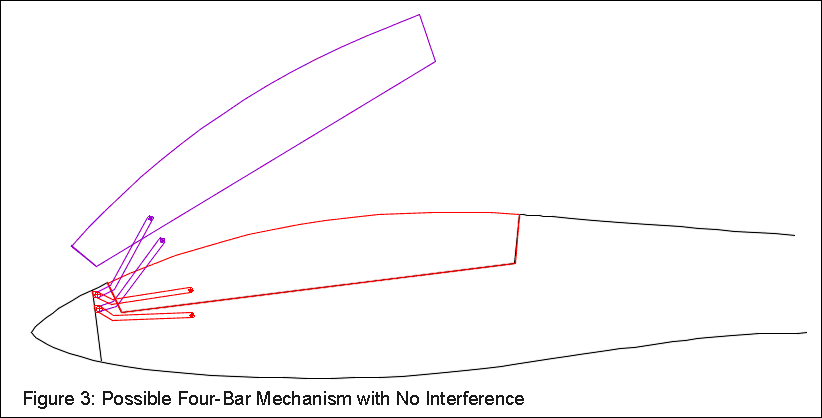
Another possibility is a four-bar mechanism such as that shown in Figure 4. Four-bar mechanisms generally connect two mechanical elements with two parallel or nearly-parallel arms and four pivots. They are called "four bar" because the two mechanical elements (in this case the canopy and the fuselage) count as bars in addition to the two arms. Anyhow, using a four-bar mechanism gives you the option of having the canopy move in a more complex motion than just a simple pivot around an axis.

As far as designing a four-bar mechanism goes, the method that I have found most useful is to just cut out pieces of cardboard, tack them together with push-pins, and see if they move the way I want them to. Actually, I usually do this in a drawing program like CorelDraw or AutoCAD, but the effect is the same: I patch something together and see what it does. If it doesn't do what I want, I change it.
As an aside, the reason that the bars in the mechanism in Figure 4 are so long is that I wanted to put the canopy frame mount as far aft as possible. This reduces the bending moment applied to the canopy frame, making it less likely that the canopy frame will flex and crack the canopy or break away from the Plexiglas. It is also possible to have a working four-bar link with much shorter arms.
Faced with an awkward no-pivot zone like that on the stock HP-18, one possible approach to placing the hinge pivot is to just change the angle of the forward canopy bow, and thus achieve a no-pivot zone that is easier to work with. This is shown in Figure 3. The dashed blue line shows the original canopy bow line, and the solid lines show the revised location.

As you can see, changing the angle of the forward canopy bow moves the no-pivot zone so that there is a much bigger area where it is OK to put a hinge pivot. With the revised canopy bow angle, it is possible to have a simple hinge pivot and simple mating surfaces with no interference. The big disadvantage to this approach is that it takes a fair amount of surgery on the fuselage and on the canopy.
If I've misstated or misrepresented anything in this article, I'd sure like to know about it so that I can fix it. I've spent more than a few odd moments staring at my fuselage pods and going over the ifs and hows of canopy hinge design, but I'm no mechanical design expert. You can always reach me at bob@hpaircraft.com.